EasyManuals Logo

Vacon NX User Manual

Vacon NX
239 pages
To Next Page IconTo Next Page
To Previous Page IconTo Previous Page
Page #180 background imageLoading...
Page #180 background image
11
vacon • 178 Non-regenerative front end
Local contacts: http://drives.danfoss.com/danfoss-drives/local-contacts/
11.3 Installation of the NFE control cables
A 24Vdc power supply for fans, fan feedback signals and PT100 temperature sensor must be
connected to the X100 connector at the NFE module.
1
Remove the protective cover to reveal the X100-connector on the power unit.
2
Connect the wires as shown in Figure 100. The 24Vdc fans require minimum 1A
current capacity. Route the cables into the NFE power unit on the top of unit.
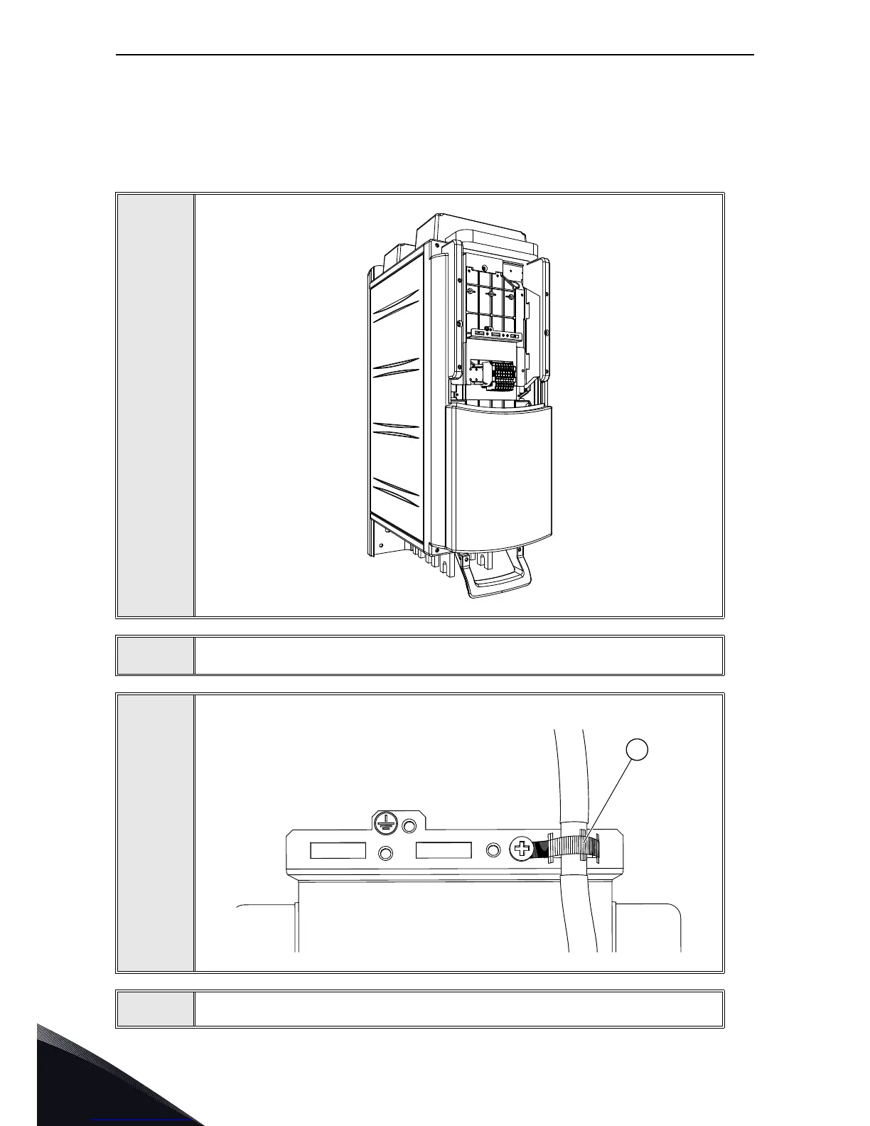
3
Using the cable clamp (1) included in the delivery of the drive, ground the shield
of the cable between the NXP control and the power unit.
4
Close the protective cover.
11712_00
11711 00
1

Table of Contents

Other manuals for Vacon NX

Questions and Answers:

Question and Answer IconNeed help?

Do you have a question about the Vacon NX and is the answer not in the manual?

Vacon NX Specifications

General IconGeneral
Product TypeAC Drive
Control MethodScalar Control
EnclosureIP00, IP21
CommunicationEthernet
SafetySTO (Safe Torque Off)
Protection FeaturesOvercurrent, Overvoltage, Undervoltage, Overtemperature, Short Circuit
Ambient Temperature Range-10°C to +50°C (with derating above +40°C)
Cooling MethodAir-cooled, Liquid-cooled

Related product manuals