EasyManua.ls Logo

Vacon NX - Page 179

Vacon NX
239 pages
To Next Page IconTo Next Page
To Previous Page IconTo Previous Page
Loading...
Non-regenerative front end vacon • 177
Local contacts: http://drives.danfoss.com/danfoss-drives/local-contacts/
11
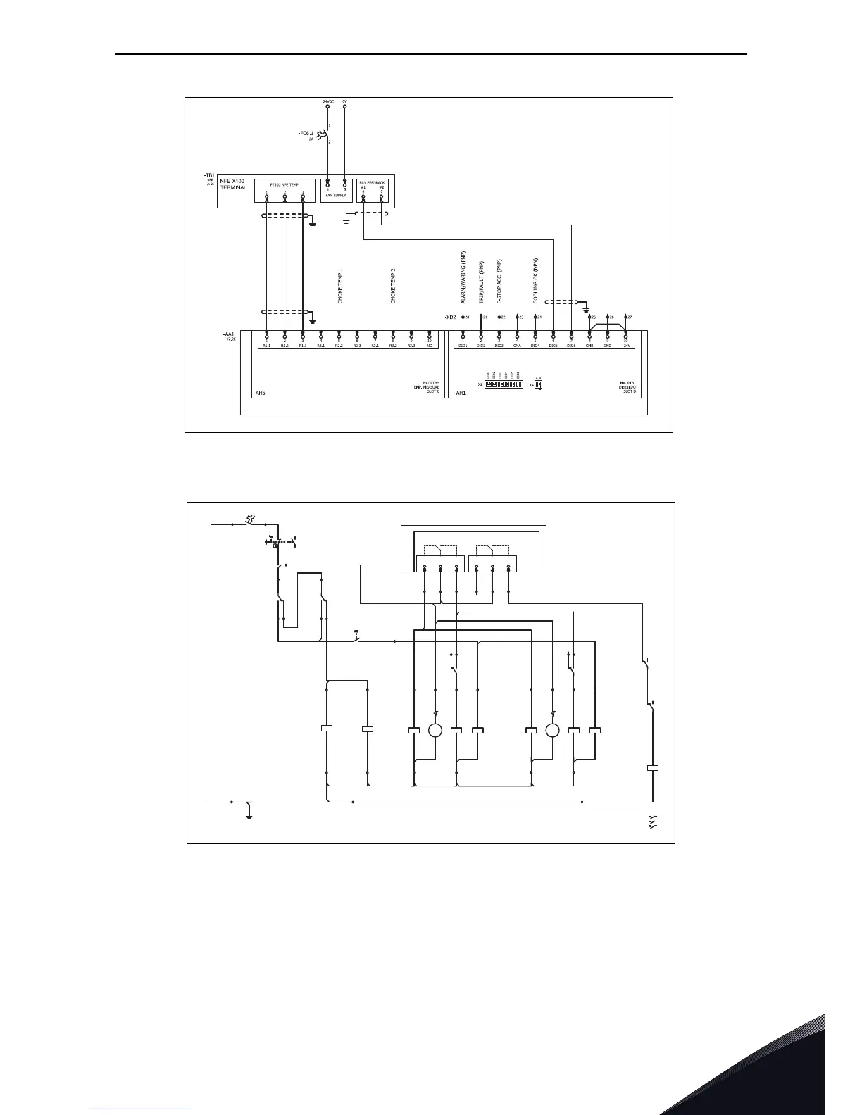
Figure 100. Wiring diagram for controls, OPTBH, OPTB1
Figure 101. Wiring diagram for controls, OPTA2
The NFE power unit, NXP Control and the external control accessories need external 24Vdc supply.
A minimum of 2A power is required to ensure proper operation. See the connection from circuit
diagrams Figure 98 - Figure 101. The cable between the NXP control and the power unit has to be
shielded and grounded using the cable clamp which is included in the delivery of the drive.
The main circuit breaker control requires typically external 230Vac, and a minimum of 2A.
11682A_uk
11683_uk
ACB UNDER VOLTAGE TRIP
ACB TRIP
M
YR
YC
YO
C11 U1 C1
R1
C2
-FC4.2
R2U2C12
M
YRYC
YO
C11 U1
C1 R1
C2
-FC4.1
R2U2C12
ACB CONTROL
SUPPLY
230V
AC L
YU
D1
D2
-FC4.1
YU
D1
D2
-FC4.2
14
13
-SF9
ACB RESET
-XD5.1
4
5
-XD5.1
3
96
95
98
-FC4.1
/1.2B
-XD5.2
4
5
-XD5.2
3
96
95
98
-FC4.2
/1.4B
9
-XD5.2
10
14
13 15
-XD5.2
6
-XD5.2
7
-XD5.1
10 14
13
15
9
-XD5.1
6
-XD5.1
7
-XD5.2
8
-XD5.1
8
46
45
48
-FC4.2
/1.4B
-XD5.2
11 12
12
-XD5.1
11
46
45
48
-FC4.1
/1.2B
-XD1
6
4
8
-XD1
5
9
12
10A
-FC6.2
7
-XD1
-PE
CHARGING CONTACTOR
DC PRE-CHARGING
12
/1.7D
34/1.7D
5
6 /1.8D
A1
A2
-QA6.1
10
-XD1
22
21
24
-FC4.1
/1.2B
22
21
24
-FC4.2
/1.4B
SUPPLY
0V
AC N
23
RO1 NO
22
RO1 C
21
RO1 NC
26
RO2 NO
25
RO2 C
24
RO2 NC
-XD2
14
15
16 17
18
19
-AF2
NXOPTA2
2xRO
SLOT B
-AA1
/2.2E
23
24
E-STOP
ACC.
11
12
-SFG1
E-STOP

Table of Contents

Other manuals for Vacon NX

Related product manuals