3
vacon • 14 Receipt of delivery
Local contacts: http://drives.danfoss.com/danfoss-drives/local-contacts/
3. RECEIPT OF DELIVERY
The standard delivery of VACON
®
NX Liquid-Cooled AC drives includes all or part of the following
components:
VACON
®
NX Liquid-Cooled AC drives have undergone scrupulous tests and quality checks at the
factory before they are delivered to the customer. However, after unpacking the product, check that
no signs of transport damages are to be found on the product and that the delivery is complete
(compare the type designation of the product to the code).
Should the drive have been damaged during the shipping, contact primarily the cargo insurance
company or the carrier.
If the delivery does not correspond to your order, contact the supplier immediately.
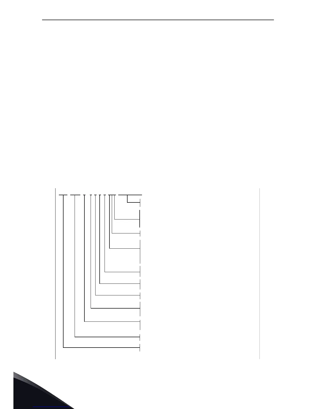
3.1 Type designation code
The type designation code for the VACON
®
NX Liquid-Cooled drives is presented below.
*) Note, the control unit of NX_8 (voltage class 8) drives need to be supplied with a external 24 Vdc power
source.
•Power unit
• Control unit
• Main line connecting hoses and
conduits (1.5 m) + aluminium
adapters for Ch5-Ch74
• Tema 1300 series fast connectors
for Ch3-Ch4
• Choke (not DC-fed inverters, type code I)
• Control unit mounting kit
• Optic fibre & cable set (1.5 m) for
control unit; Optic sets in different
lengths also available
• Optic fibre cable set for 2*CH64/CH74:
1.8 m/11 fibres (Power module 1) and
3.8 m/8 fibres (Power module 2)
NXP 0000
A 0 N 1 SWV A1A20000C3
5
Option boards; each slot is represented by two characters where:
A = basic I/O board, B = expander I/O board,
C = fieldbus board, D = special board
Hardware modifications; Supply - Mounting - Boards
F = Fiber connection/standard (from CH61)
G = Fiber connection/varnished (from CH61)
S = Direct connection/standard
V = Direct connection/varnished
W = Liquid-cooled module with aluminium heatsink
P = Liquid cooled module with nickel-coated aluminium heatsink
I = Inverter unit; DC-supply
S = Standard supply; 6-pulse connection with chokes
N = Standard supply; 6-pulse connection without chokes
T = 12-pulse connection (with chokes)
U = 12-pulse connection (without chokes)
2 = Active front end unit
8 = Brake chopper unit
Brake chopper
0 = no brake chopper
1 = internal brake chopper (CH3, CH72 (6-pulse) & Ch74 only)
EMC emission level:
N = No EMC emission protection; to be installed in enclosures.
T = Fulfils standard 61800-3 for IT networks.
Control keypad:
A = standard (alpha-numeric)
B = neutral (no local control keypad)
F = dummy panel
G = graphic display
Nominal mains voltage (3-phase):
5 = 380–500 V ac, 6 = 525–690 V ac (640–1100 Vdc),
8 = 525–690 Vac (640–1200 Vdc). (CH6X only). *)
Nominal current (low overload)
0007 = 7 A, 0022 = 22 A, 0205 = 205 A etc.
Product range: NXP = high-performance, NXB = brake chopper unit,
NXA = Active front end unit, NXN = Non-regenerative front end unit
Enclosure class:
0 = IP00
3035B_uk