Electrical cabling and connections vacon • 97
Local contacts: http://drives.danfoss.com/danfoss-drives/local-contacts/
6
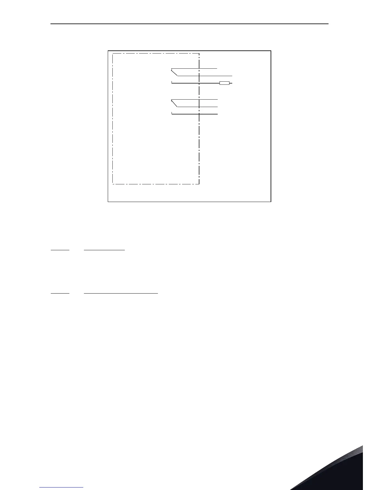
Figure 45. General wiring diagram of the basic relay board (OPT-A2)
6.2.2.1
Control cables
The control cables must be at least 0.5 mm
2
screened multicore cables, see Table 35. The
maximumterminal wire size is 2.5 mm
2
for the relay terminals and 1.5 mm
2
for other terminals.
6.2.2.2
Galvanic isolation barriers
The control connections are isolated from the mains potential and the GND terminals are
permanently connected to ground. See Figure 46.
The digital inputs are galvanically isolated from the I/O ground. The relay outputs are additionally
double-isolated from each other at 300 VAC (EN-50178).
RO1/1
1/2
RO1/3
RO2/1
2/2
RO2/3
ac/dc
21
22
23
24
25
26
NX6_6.fh8
Switching:
<8A/24Vdc,
<0.4A/125Vdc,
<2kVA/250Vac
Continuously:
<2Arms
Basic relay board
OPT-A2
11355_uk