EasyManuals Logo

Vacon NX User Manual

Vacon NX
239 pages
To Next Page IconTo Next Page
To Previous Page IconTo Previous Page
Page #59 background imageLoading...
Page #59 background image
Installation vacon • 57
Local contacts: http://drives.danfoss.com/danfoss-drives/local-contacts/
5
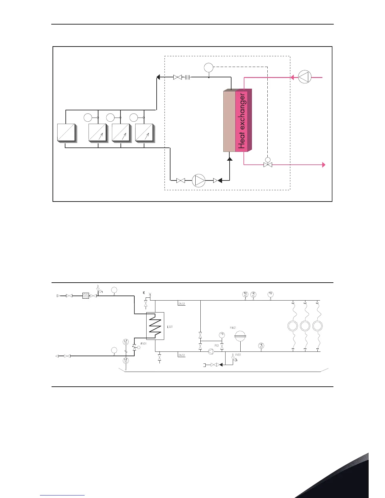
Figure 24. Example of cooling system
We recommend to equip the cooling system with pressure and flow supervision (FE). The flow
supervision can be connected to digital input function External fault. If the coolant flow is found too
low, the AC drive will be stopped.
The flow supervision and other actuators, e.g. a constant flow valve, are available as options. The
options must be mounted at the junction of the main line and the branching line to the element,
indicated with an asterisk (*) in the figure above.
Figure 25. Example: PI-diagram of the cooling system and the connections
=
=
=
=
18.C
26.1ºC
30.0ºC
34.5ºC
FE FE FE
****
*
*
*
*
TE
11332_uk
Cooling water inlet
Frequency converters
Cooling water outlet
11333_uk

Table of Contents

Other manuals for Vacon NX

Questions and Answers:

Question and Answer IconNeed help?

Do you have a question about the Vacon NX and is the answer not in the manual?

Vacon NX Specifications

General IconGeneral
Product TypeAC Drive
Control MethodScalar Control
EnclosureIP00, IP21
CommunicationEthernet
SafetySTO (Safe Torque Off)
Protection FeaturesOvercurrent, Overvoltage, Undervoltage, Overtemperature, Short Circuit
Ambient Temperature Range-10°C to +50°C (with derating above +40°C)
Cooling MethodAir-cooled, Liquid-cooled

Related product manuals