List of Figures
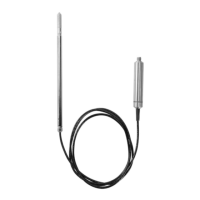
Figure 1 GMP252 Probe Parts..........................................................................................11
Figure 2 ASM212011SP Flow-through Adapter...........................................................13
Figure 3 Probe Cuvette with Mirror and Sensor Chips............................................ 14
Figure 4 CO
2
Measurement in the Measurement Cuvette.......................................15
Figure 5 Example of Analog Output Overrange Behavior .................................... 19
Figure 6 GMP252 Dimensions.........................................................................................21
Figure 7 Probe with 243261SP Mounting Flange......................................................22
Figure 8 Probe in 243257SP Mounting Clips..............................................................23
Figure 9 Probe with ASM212017SP Spray Shield ..................................................... 23
Figure 10 GMP252 in DTR250 Radiation Shield .........................................................24
Figure 11 GMP252 Installation with DTR250A Pole Mounting Kit ........................24
Figure 12 Example of analog output overrange behavior.......................................48
Figure 13 Connecting Probe to Insight...........................................................................61
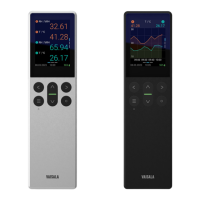
Figure 14 GMP252 Attached to Indigo Transmitter................................................... 63
Figure 15 Desktop and Mobile Example Views...........................................................64
Figure 16 Serial Number on Probe Body (GMP251 Example)................................. 66
Figure 17 Attaching Probes and Cables to Indigo......................................................67
Figure 18 Enabling and Accessing Indigo's Wireless Configuration
Interface.............................................................................................................. 68
Figure 19 Indigo Login View............................................................................................ 69
Figure 20 Wireless Configuration Interface, Desktop Browser View.................... 70
Figure 21 Indigo 201 Analog Output Configuration Options................................... 71
Figure 22 Clearing Analog Output Settings ................................................................72
Figure 23 Selecting Indigo 201 Analog Output Mode............................................... 73
Figure 24 Relay Configuration Options......................................................................... 75
Figure 25 Calibration Menu Main View.......................................................................... 78
Figure 26 Start Calibration Button..................................................................................79
Figure 27 MI70 Basic Display........................................................................................... 85
Figure 28 MI70 Indicator Parts.........................................................................................87
Figure 29 CO
2
Reading with Tcomp and Pcomp on MI70 Screen..........................89
Figure 30 Probe Compensation Settings on MI70 Screen....................................... 89
Figure 31 Opening the Filter............................................................................................94
Figure 32 DRW244827SP Calibration Adapter with Probe Inserted.................... 97
Figure 33 GMP252 Dimensions...................................................................................... 107
Figure 34 243261SP Mounting Flange Dimensions...................................................107
Figure 35 243261SP Mounting Flange Dimensions, Cross Section...................... 108
Figure 36 DRW244827SP Calibration Adapter Dimensions..................................108
Figure 37 ASM212017SP Spray Shield Dimensions...................................................109
Figure 38 GMP252 Spray Shield Cross Section......................................................... 109
Figure 39 DTR250 Radiation Shield Dimensions (mm)........................................... 110
Figure 40 DTR250A Pole Mounting Kit Dimensions (in mm [inch])......................111
GMP252 User Guide M211897EN-D
4

 Loading...


