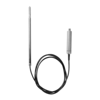
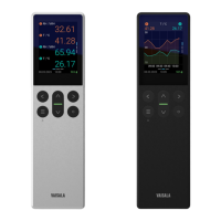
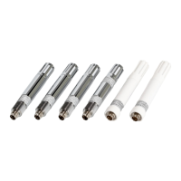
Figure 23 Selecting Indigo 201 Analog Output Mode
7.8 Using Modbus with Indigo 202
Indigo 202 digital transmitters are designed for Modbus RTU (RS-485) communication.
There are 2 groups of Modbus register addresses in use in Indigo 202: probe registers and
Indigo registers. The probe registers are received from the connected probe, and are
organized according to the probe's register map. Indigo registers include
transmitter-
specific information.
Received Modbus requests for register operations are treated in two dierent ways
depending on the register address. Addresses above DFFF
hex
(that is, Indigo registers) are
handled as normal requests. Lower addresses (that is, probe registers 0000
hex
... DFFF
hex
)
are passed to the measurement probe, and the response from the probe is again passed to
original Modbus client. Indigo can also have a cache for commonly requested registers
(Measurement registers).
The maximum response delay is 2 seconds (when data content needs to be fetched from the
probe). The minimum delay between requests is 10 ms.
For more details on the information relayed within Indigo 202
(transmitter-specific)
Modbus registers, see Indigo 202 Digital Transmitter User Guide.
Table 46 Indigo 202 Modbus Registers
Address Name Data Type
Probe registers (according to the connected probe's register map)
1)
0000
hex
First measurement probe address
DFFF
hex
Last measurement probe address
Indigo registers
E000
hex
Status 16-bit
E001
hex
Notification and error bits 16-bit
Chapter 7 – Using GMP252 with Indigo Transmitters
73

 Loading...


