7. Using GMP252 with Indigo
Transmitters
7.1 Indigo Overview
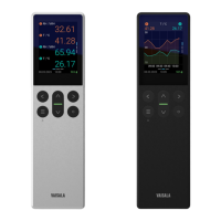
Figure 14 GMP252 Attached to Indigo Transmitter
1 3.5” TFT LCD color display: non-display option with LED available for certain models.
2 Probe locking wheel: insert probe, hold in place and turn the wheel counterclockwise.
3 Probe orientation mark: insert the probe with the orientation mark facing out.
4 Wireless configuration interface (WLAN) activation button.
5 Rubber lead-through with strain relief. Cable feedthrough option also at back of
transmitter.
6 Input/output cable.
Chapter 7 – Using GMP252 with Indigo Transmitters
63

 Loading...