3-98
V
ARI
*L
ITE
®
-
VL4
W
ASH
L
UMINAIRE
S
ERVICE
M
ANUAL
CONFIDENTIAL 02.9628.0010
7-Oct-97
d. While holding up luminaire head with one hand, reach under
yoke bearing and disconnect black, 26-pin connector from
motherboard marked YOKE A MB-P4. Connector is
located next to connector marked YOKE B.
e. At rear of chassis, behind power supply, disconnect 26-pin
black connector from motherboard header marked YOKE B
MB-P5.
f. Remove yoke bearing frame from chassis.
Step 7. Remove input connector.
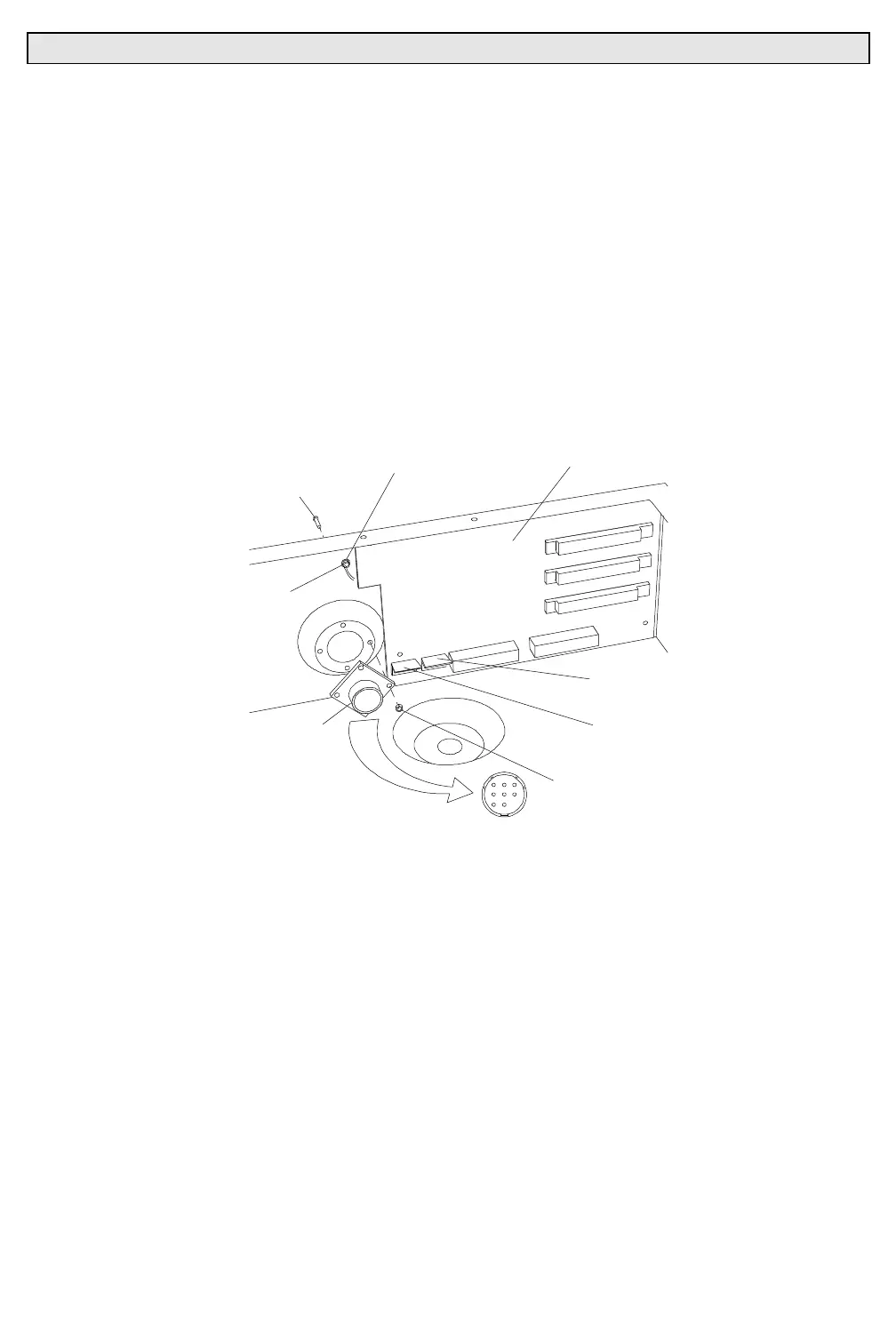
a. At bottom left of motherboard, disconnect 5-pin MTA
connector from header DATA MB-P9 (
Figure 3-38
).
CONNTB
CONNECTOR KEYING
4-40 KEPS NUT
FIVE-PIN MTA100
CONNECTOR
DATA MB-P9
FIVE-PIN MTA100
CONNECTOR
PAN MB-P7
INPUT CONNECTOR
6-32 KEPS NUT
MOTHERBOARD
GROUNDING WIRES
RING LUG
4-40X5/16"PPB SCREW
Figure 3-38. Input Connector Removal and Replacement
b. At input connector, at outside of chassis, remove four
4-40x5/16"PPB screws and 4-40 KEPS nuts that secure
square flange receptacle to chassis.
c. At input connector green grounding wires, using 5/16 inch
nutdriver, remove 6-32 KEPS nut and ring lug from PEM
nut on rear of chassis.
d. Using pin removal tool, remove pin contacts from faulty
receptacle and remove receptacle.