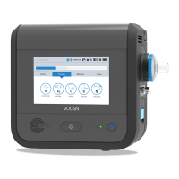
The Touchscreen
VentecLife.com 52
The Status Bar
The status bar remains at the top of the screen during V*Home use. The status bar includes the following indicators:
Description
1 Alarm indicator. If an alarm condition occurs, the name of the alarm will display, along with a visual (color) indicator of
alarm severity. Press the alarm indicator at any time to access the V*Home Alarm and Event Logs. See “The Alarm
Log” on page 91 and “The Event Log” on page 92 for more information.
2 Therapy indicator. The active therapy (Ventilation, Oxygen, and/or Nebulizer) will appear as an icon.
3 Ventilation Mode indicator. The active Ventilation Mode control setting displays as an abbreviation. See “V*Home
Ventilation Modes” on page 39 for a description of each available mode.
4
Clinician Unlock indicator. When V*Home is in Clinician Unlock mode, an unlocked padlock appears on the top of the
touchscreen. While V*Home is locked, a locked padlock is displayed.
5
Screen Lock button. Press and hold the icon for 3 seconds to lock or unlock the V*Home touchscreen. When locked,
an orange “X” will appear in the icon, and the screen will be protected from accidental button presses.
6
External power indicator. A plug icon will appear and remain on the top of the screen when V*Home is connected to
external power.
7 Removable battery indicators. Two battery icons indicate the charging status and remaining battery power of each of
the two removable batteries. The icon on the left indicates the status of the battery installed in the left battery well.
The icon on the right indicates the status of the battery installed in the right battery well. See “Glossary of Indicators”
on page 139 for more information.
8 Internal battery indicator. A battery icon indicates the charging status and remaining battery power of the internal
battery. If the icon ll is below 50% (turns yellow) or below 33% (turns red), nd an external source of power
immediately. See “Glossary of Indicators” on page 139 for more information.
9 Patient triggered indicator. This icon will appear if the current breath is triggered by patient effort to breathe.
10 Low Pressure alarm indicator. This icon marks the set Low Pressure alarm limit.
11 Pressure monitor. This pressure manometer will increase (to the right) and decrease (to the left) as breaths are delivered
to the patient. The dark blue bar represents the pressure delivered during the current breath. The light blue bar
represents the peak pressure delivered during the previous breath.
12 High Pressure alarm indicator. This icon marks the set High Pressure alarm limit.
0 5 10 15 20 25 30L H
No Alarms
PRESSURE (cmH20)
SIMV-VOL
V O
1 2 3 4 5 6 7 78
9 10 11
12

 Loading...