54
PROCEdURE 18. REASSEMBLE THE CONSOLE
Prior to reassembling the console, review the section Workmanship Standards on page74. If any of the
console components require replacement according to the guidance in that section, then replace those
components during this reassembly procedure.
QUANTITY PART # DESCRIPTION
Parts
AR 0122‑0003 Bottom cover
AR 0141‑0120 BVI3000 PCB assembly
1 0180‑0140 Ferrite suppressor
8 0261‑0008 Hide screws (#4‑40, ¼‑in, machine)
5 0261‑0030 PCB screw, medium (#4‑20,
3
/8‑in, self‑tapping)
1 0261‑ 0012 PCB screw, long (#4‑40, 1‑in, machine)
6 or 9 0261‑0008 PCB screw, short (#4‑40, ¼‑in, machine)
7 0261‑0043 Window screw with washer (#4,
3
/4‑in, self‑tapping)
AR 0122‑0019 Overmold
4 0261‑0031 Overmold screw, large (#8‑16,
3
/8‑in, self‑tapping)
6 0261‑0030 Overmold screw, small (#4‑20,
3
/8‑in, self‑tapping)
4 0261‑ 0013 Bottom cover screw (#8‑32,
5
/8‑in, machine)
2 0260‑0283 Bottom cover screw (#4,
3
/4‑in, self‑tapping)
4 0122‑0014 Console foot
Tools
AR — Phillips bit
2 — Bar clamp
AR 0 410 ‑ 0 011 Double‑sided tape
AR — Tweezers or other small instrument
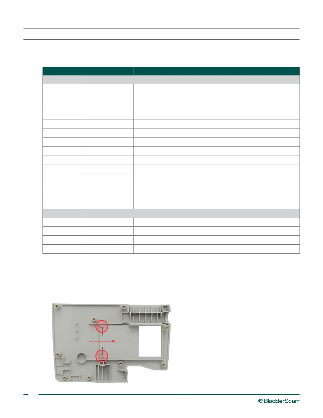
ATTACH THE HIdE
1. If you did not remove the hide, skip to Step6.
2. Ensure that the two tabs on the back of the printer door are facing up and are closest to the center of
the hide, and then slide the door partially closed.
 Loading...