55
Verathon Service Partner Manual: Repair & Replacement
3. Hold the printer door in place, and then place the hide on the top cover.
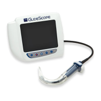
4. Holding the hide in place, flip the top cover over.
5. Using a Phillips bit and (8) hide screws (0261‑0008), secure the hide in place.
INSTALL THE PCB ASSEMBLY ANd FERRITE
6. If you did not remove any of the screws securing the PCB assembly in place, skip to Step19.
7. If you did not remove the analog PCB, skip to Step15.
8. Verify that the LCD is clean and free of dust, lint, or fingerprints.
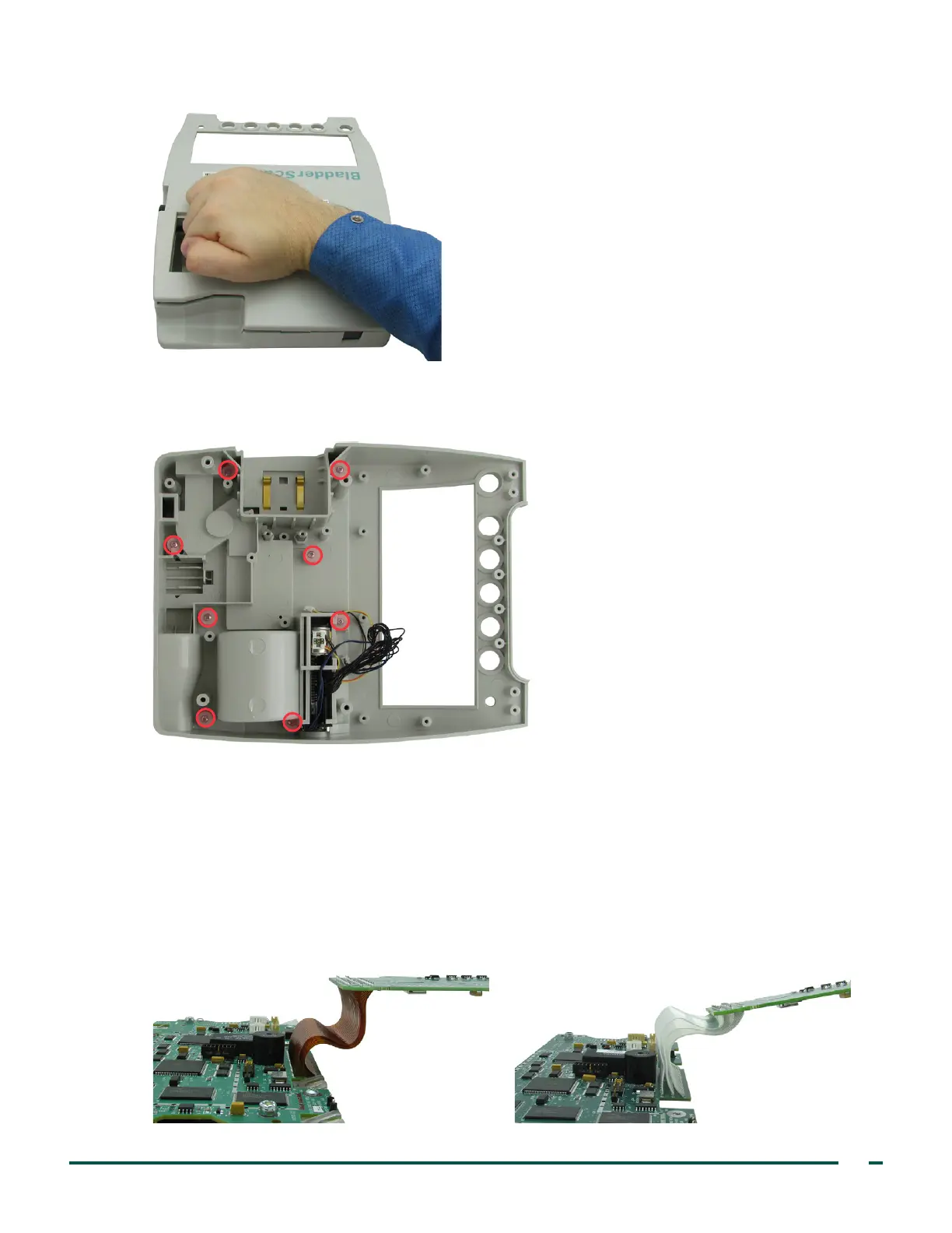
9. Bend the ribbon cable between the PCBs in the assembly as shown in the following images.
Figure 18. Curve for brown ribbon cable Figure 19. Curve for white ribbon cable
 Loading...