Figure 3-69 Saved successfully
2) Click on Refresh Query Record later to view the results.
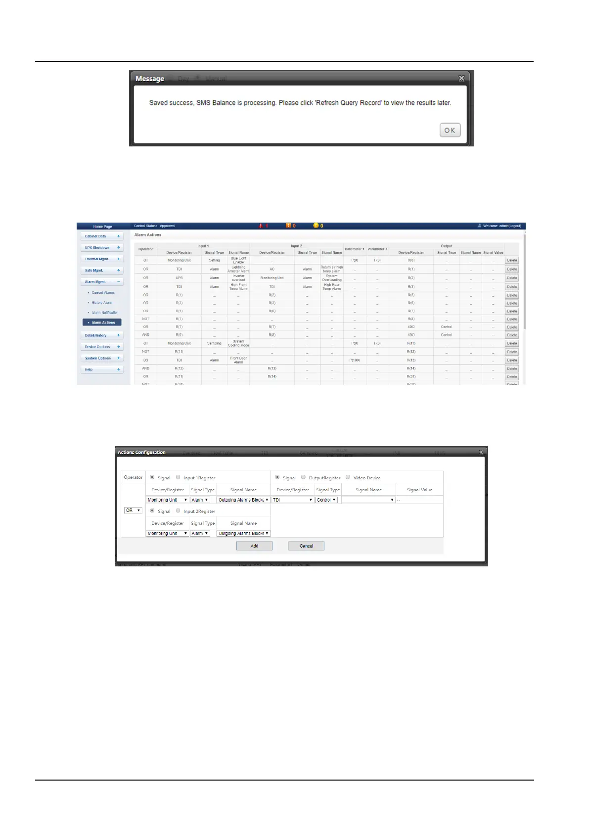
⚫ Alarm Actions
Click the Alarm Actions submenu under the Alarm Mgmt. menu to get the alarm linkage function. The page shown
in the Figure 3-70 pops up.
Figure 3-70 Alarm linkage configuration 1
⚫ Linkage function
The list of key to Operator/Symbol in the figure shows all the commands and their functions. Click the Add button to
add a new alarm linkage expression, otherwise click the Cancel button as shown in the Figure 3-71.
Figure 3-71 Alarm linkage configuration 2
First, select an operator, for example, "OR", and the expression is "Signal 1 [Input 1 Register] or Signal 2 [Input 2
Register] = Signal 3 [Output Register]".
Second, when the input or output parameter in the expression is selected as the signal, first select the device name
in the Device/Register drop-down list, then select the signal type in the Signal Type drop-down list, and finally select
the Signal name in the Signal Name drop-down list. Signals 1, 2, 3 may be any signal available in an intelligent
monitoring system.
Finally, when the parameter in the expression is selected as a Register, you need to select the name of the
corresponding register, such as R(0), R(1), etc., as shown in the Figure 3-72.
If you click the Add button, as shown in the Figure 3-73, the alarm linkage expression has been added, click the
Save and Apply button to make it effective. Click the Delete button to delete the alarm linkage expression and click
the Save and Apply button to make it effective.