Vertiv | NetSure™ 8200 Series -48 VDC Power System Installation Manual (IM582140000) | Rev. A
Connector Locations on Primary Power/Distribution Bay and Primary Power Only Bay Control Shelf
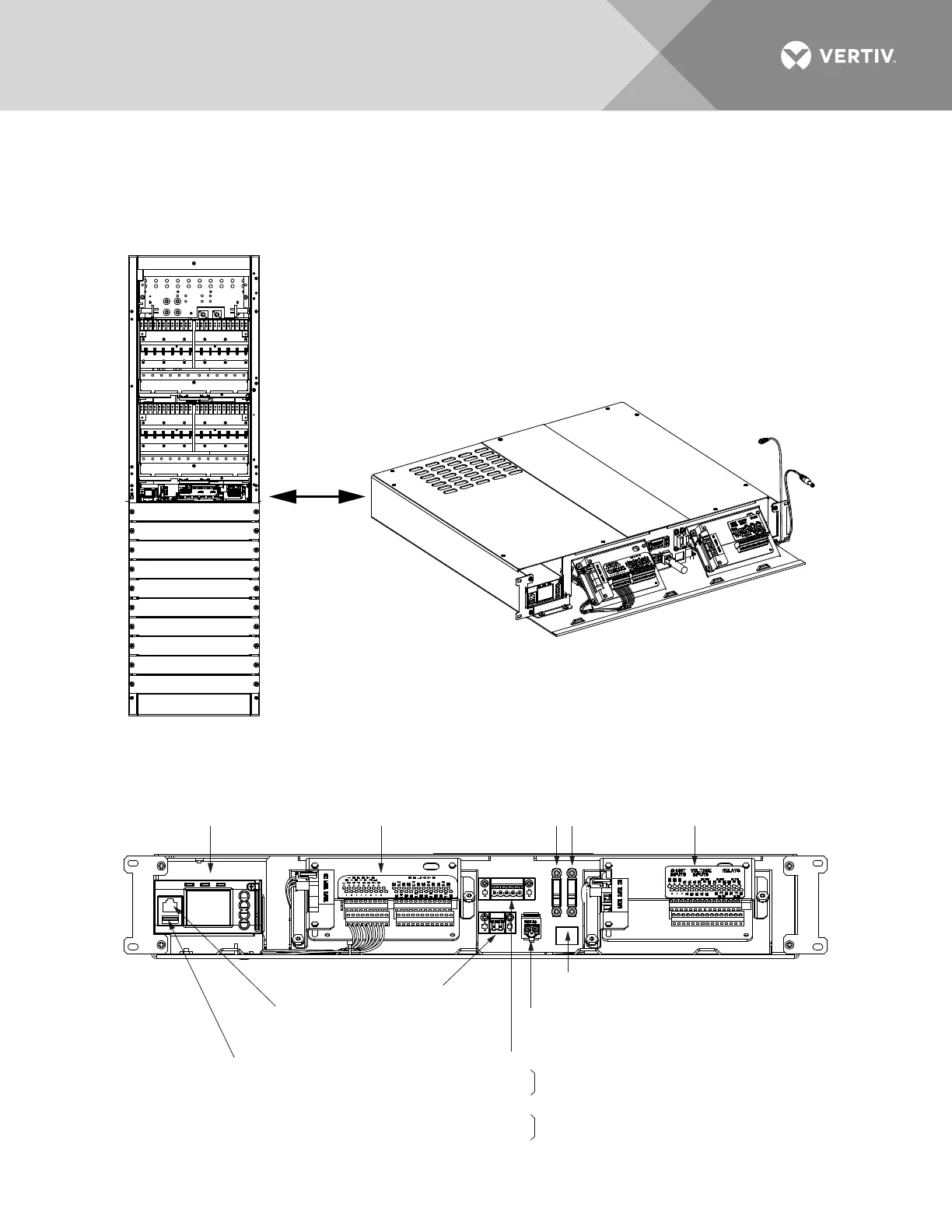
Refer to Figure 81 for a connector location illustration.
Figure 81:
Connector Locations – Primary Power/Distribution Bay and Primary Power Only Bay Control Shelf
Control Shelf
Primary Power/Distribution Bay
Primary Power Only Bay Similar
Front door removed in illustration for clarity only.
Primary Bay Control Shelf
Ethernet Port (NCU)
(Front Door Display)
TB2
(for future use)
TB1
RS-485 Port 1 / Port 2
TB1-1 RS485_1A
TB1-2 RS485_1B
TB1-3 C_GND
TB1-4 RS485_2A
TB1-5 RS485_2B
1 5
TB1
TB2
CAN Port
(to supplemental bay)
10Base-T Ethernet Port (IB4 Board)
(Local Area Network)
NCU
Controller
IB2
Controller
Interface Board
EIB
Controller Extended
Interface Board
USB Port
F1
Power to
Distr. DSM
(3A)
F2
Power to
Touch
Screen
(1-1/3A)
South Bound Port
North Bound Port

 Loading...


