EasyManuals Logo

Vertiv NetSure 8200 Series Installation Manual

Vertiv NetSure 8200 Series
198 pages
To Next Page IconTo Next Page
To Previous Page IconTo Previous Page
Page #196 background imageLoading...
Page #196 background image
Vertiv | NetSure8200 Series -48 VDC Power System Installation Manual (IM582140000) | Rev. A
196
Checking System Status
Procedure
1. Observe the status of the indicators located on the bay, controller, and rectifiers. If the system is
operating normally, the status of these is as shown in Table 16.
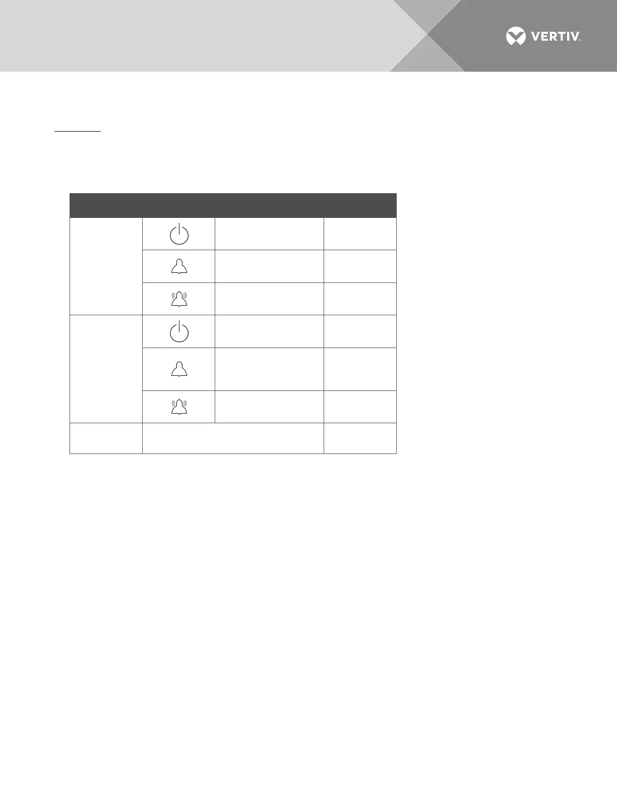
Table 16:
Status and Alarm Indicators
Component Indicator Normal State
NCU
Status (Green) On
Minor Alarm (Yellow) Off
Critical or Major
Alarm (Red)
Off
Rectifiers
AC/Identify (Green) On
Protection Alarm
(480V input rectifier
only) (Yellow)
Off
Fail Alarm (Red) Off
Bays
Bay Alarm indicator
(located on outside of door at top)
On (Green)

Table of Contents

Other manuals for Vertiv NetSure 8200 Series

Questions and Answers:

Question and Answer IconNeed help?

Do you have a question about the Vertiv NetSure 8200 Series and is the answer not in the manual?

Vertiv NetSure 8200 Series Specifications

General IconGeneral
BrandVertiv
ModelNetSure 8200 Series
CategoryPower Supply
LanguageEnglish

Related product manuals