Vertiv | NetSure™ 8200 Series -48 VDC Power System Installation Manual (IM582140000) | Rev. A
Connecting Power/Distribution Bay Rectifier Mounting Position AC Input Connectors to
PDSC (Lists 102 and 112 Only)
Procedure
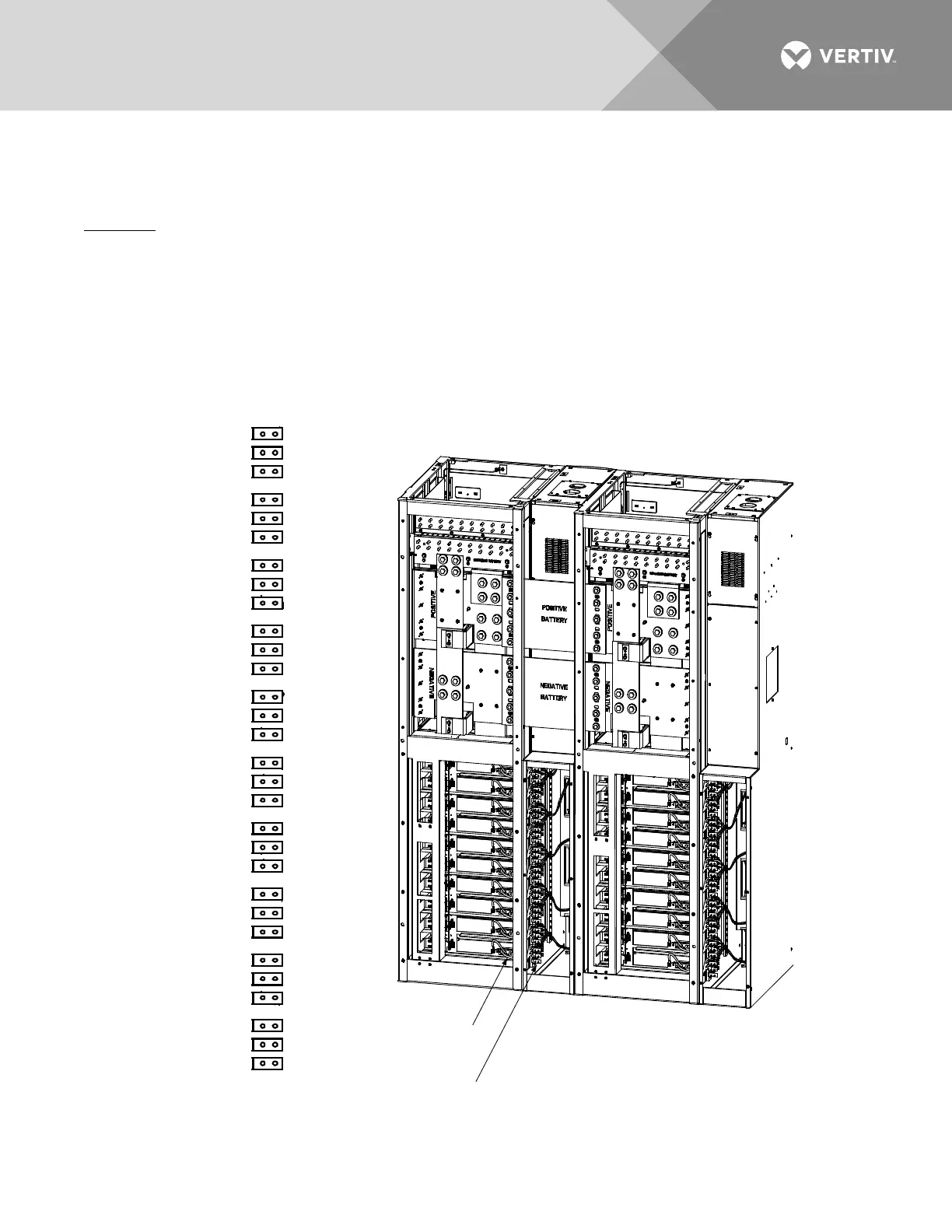
1. Refer to Figure 22, and feed the wires from the rectifier mounting position AC input connectors located
in a power/distribution bay through the side of the rectifier mounting position AC input cover and into
the PDSC. Connect the wires to the appropriate connectors provided in the PDSC. Observe the labels
on the wires (A, B, C). Torque each connection to 23 in-lbs.
2. Repeat this step for each bay.
Figure 22:
Connecting Rectifier Mounting Position AC Input Connectors to PDSC (Lists 102 and 112 Only)
Power/Distribution
Bay
Power/Distribution
Bay
PDSC
PDSC
Row of PDSC PCU
AC Input Connectors
Connectors
in PDSC
to
PCU Mtg.
Pos. #1
to
PCU Mtg.
Pos. #2
to
PCU Mtg.
Pos. #3
to
PCU Mtg.
Pos. #4
to
PCU Mtg.
Pos. #5
to
PCU Mtg.
Pos. #6
to
PCU Mtg.
Pos. #7
to
PCU Mtg.
Pos. #8
to
PCU Mtg.
Pos. #9
to
PCU Mtg.
Pos. #10
Torque to
23 in-lbs.
A
B
C
A
B
C
A
B
C
A
B
C
A
B
C
A
B
C
A
B
C
A
B
C
A
B
C
A
B
C
Row of PCU Mtg. Pos.
AC Input Connectors

 Loading...


