Vertiv | NetSure™ 8200 Series -48 VDC Power System Installation Manual (IM582140000) | Rev. A
Bay Frame Grounding Connections
NOTE! Refer to System Application Guide SAG582140000 for recommended wire size and crimp lug.
Lugs should be crimped per lug manufacturer’s specifications. For bay grounding requirements; refer to
the National Electrical Code, applicable local codes, and your specific site requirements.
Procedure
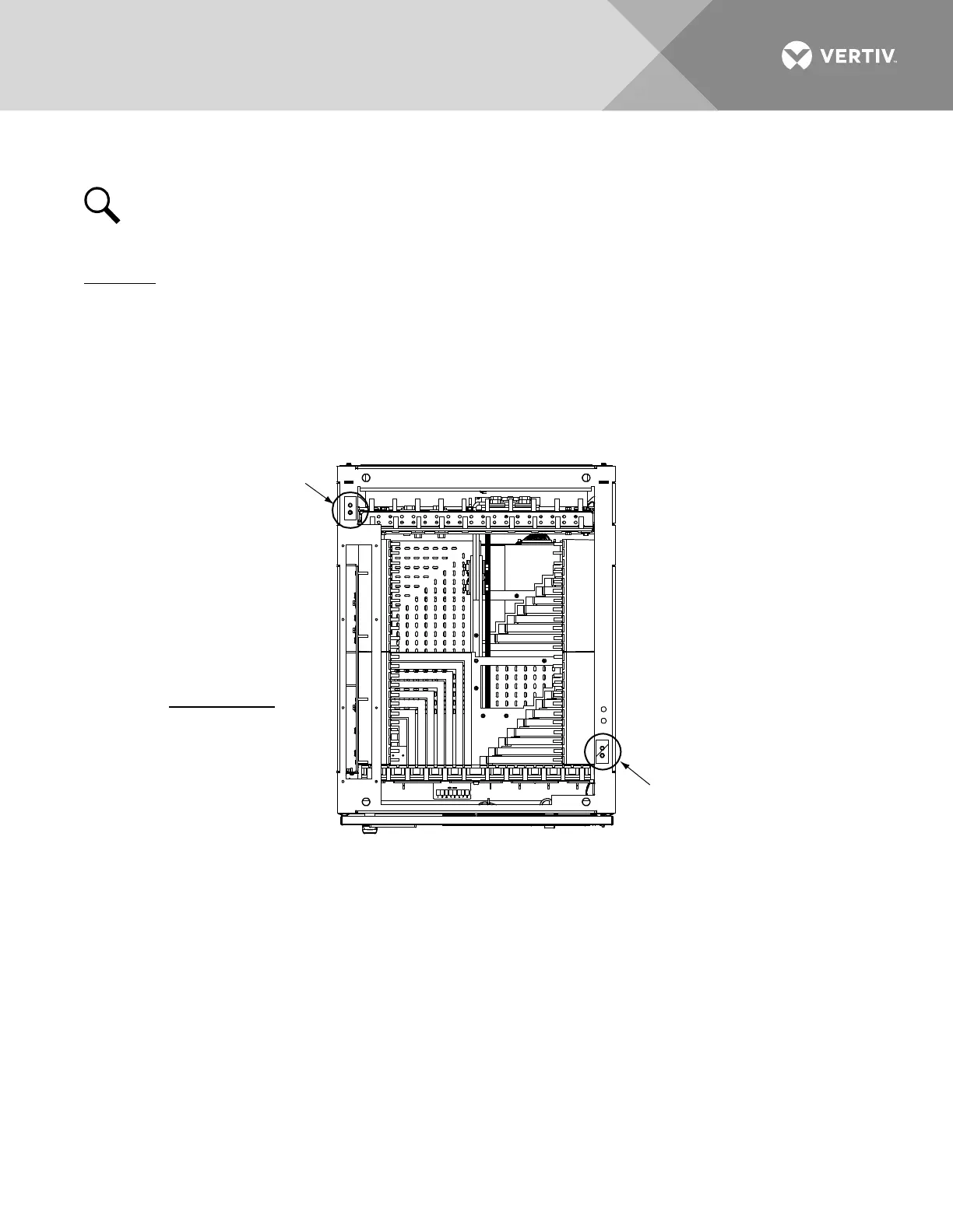
1. Located on the top of each bay are two to four sets of captive nuts (1/4-20 on 5/8" centers) or holes.
Attach customer grounding network leads to these using customer supplied two-hole lugs, mounting
bolts, and hardware. Recommended torque is 60 in-lbs when using 1/4-inch hardware and a Belleville
lock washer. Refer to Figure 92 and Figure 93 for location.
Figure 92:
Power/Distribution and Power Only Bay Frame Grounding Connection Locations
Two holes with 1/4-20 captive
nuts provided for installation of
customer provided two-hole lug
with 1/4" bolt clearance holes
on 5/8" centers
Two holes with 1/4-20 captive
nuts provided for installation of
customer provided two-hole lug
with 1/4" bolt clearance holes
on 5/8" centers
Top View
Recm. Torque
1/4" Hardware
using Belleville
Lock Washer
60 in-lbs.
Power/Distribution Bay Shown,
Power Only Bay Similar

 Loading...


