54 030624.13
vetus® Electronic engine remote control
Follow the steps from 1 to 8 as reported here below:
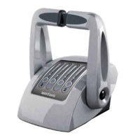
1. Verify that the actuator’s throttle lever is at minimum position, as depicted in the picture here below (1). The lever
should be at 10 mm from the eyelet, otherwise enter into the jog programming mode and move the actuator’s le-
ver to this position. For this operation follow steps from 1 to 7 section 11.1. The minimum speed throttle position is
parameter “UL”.
2. Verify that the position of the throttle lever is in idle position on the motor side as described at section 8.2.1.If this is
the case, at the actuator side the rod should be inside the push-pull cable (minimum stroke cable condition). Then
screw the eyelet (h) onto the cable’s rod (2).
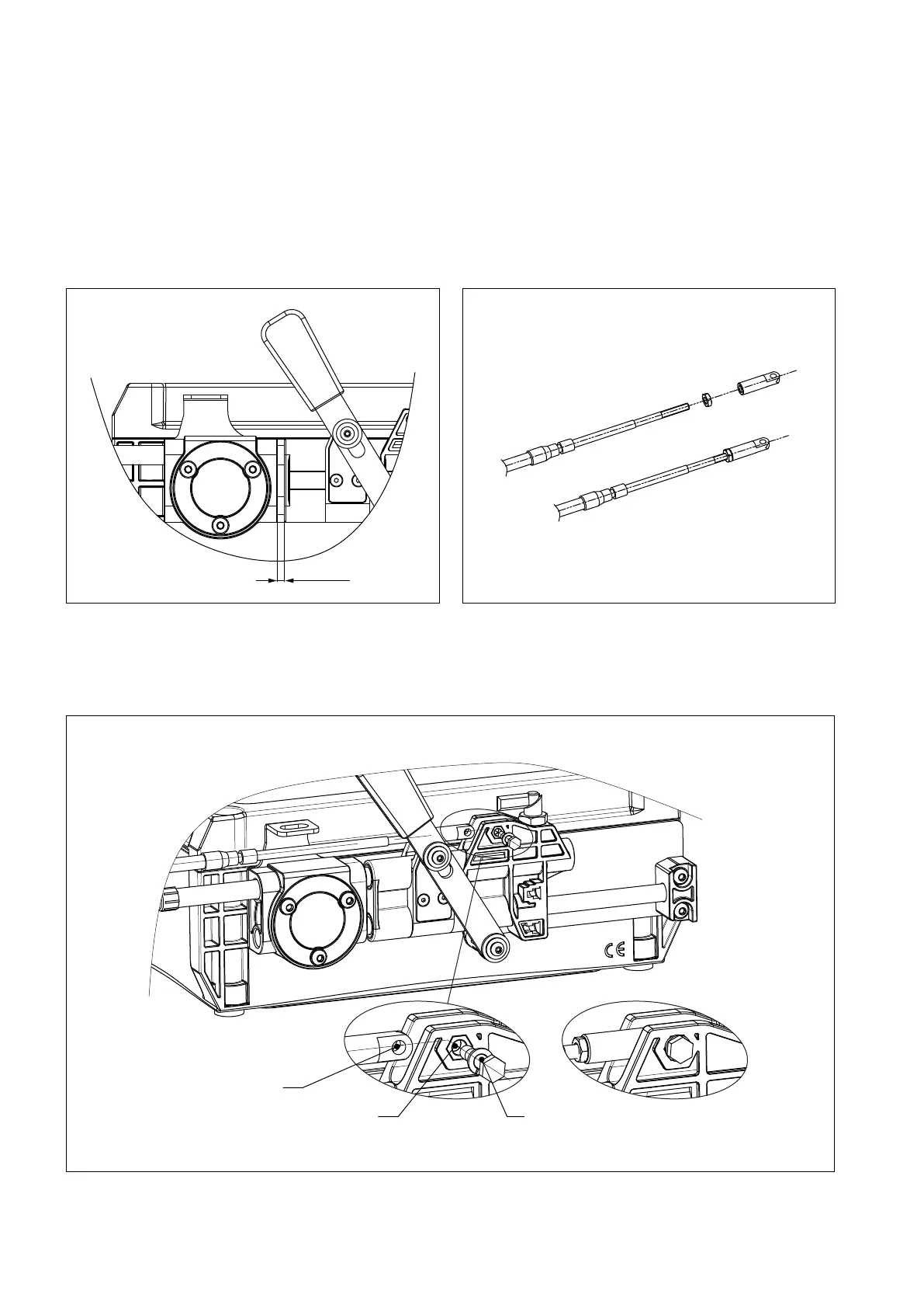
3. Align the eyelet on the push-pull cable (H1) with the hole of the plastic slider (H2). Insert the screw (+ elastic washer)
and fasten it.
5 (
3
/
16
”)
H1
H2 a
1.
3.
2.