030624.13 55
vetus® Electronic engine remote control
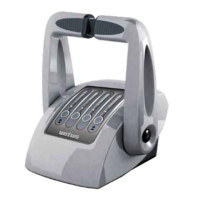
4. Insert the groove of the push-pull cable fitting between the blade (g) and the black aluminium cube (e).
4A
6A
5A
4B
6B
5. Insert the push-pull cable into the slot of the bracket (d). Check that the fixing cube is centred with respect to the
slot on the bracket.
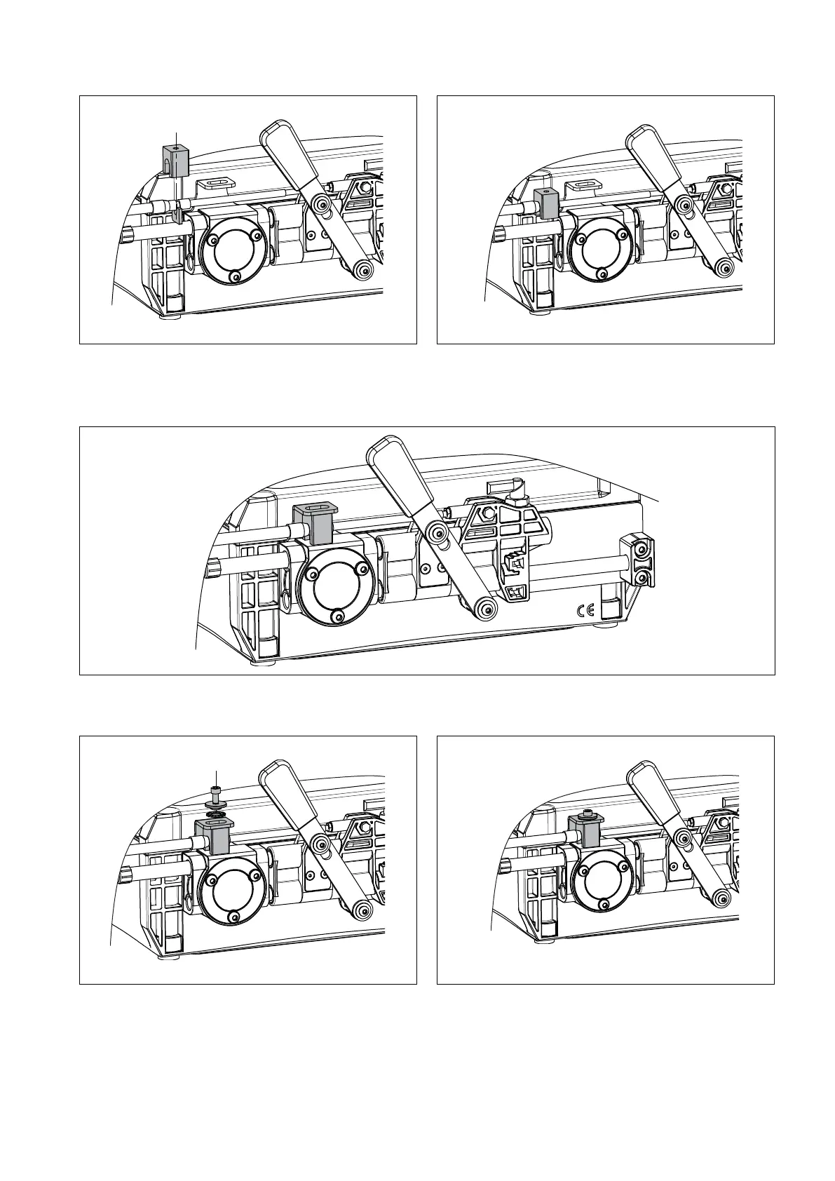
6. Fix the black aluminium cube (e) against the bracket (d) using the fixing screw (c).
7. If the fixing position is not correct, tune the push-pull cable in such a way that when the cable is at its minimum, the
fixing screw is aligned with the notch on the slot.
8. Verify and eventually tune again minimum speed position (UL) and set maximum speed position (UH). For these
operations look at section 11.1