Electrical Troubleshooting Procedures LTC Repair
wc_tx000429gb.fm 130
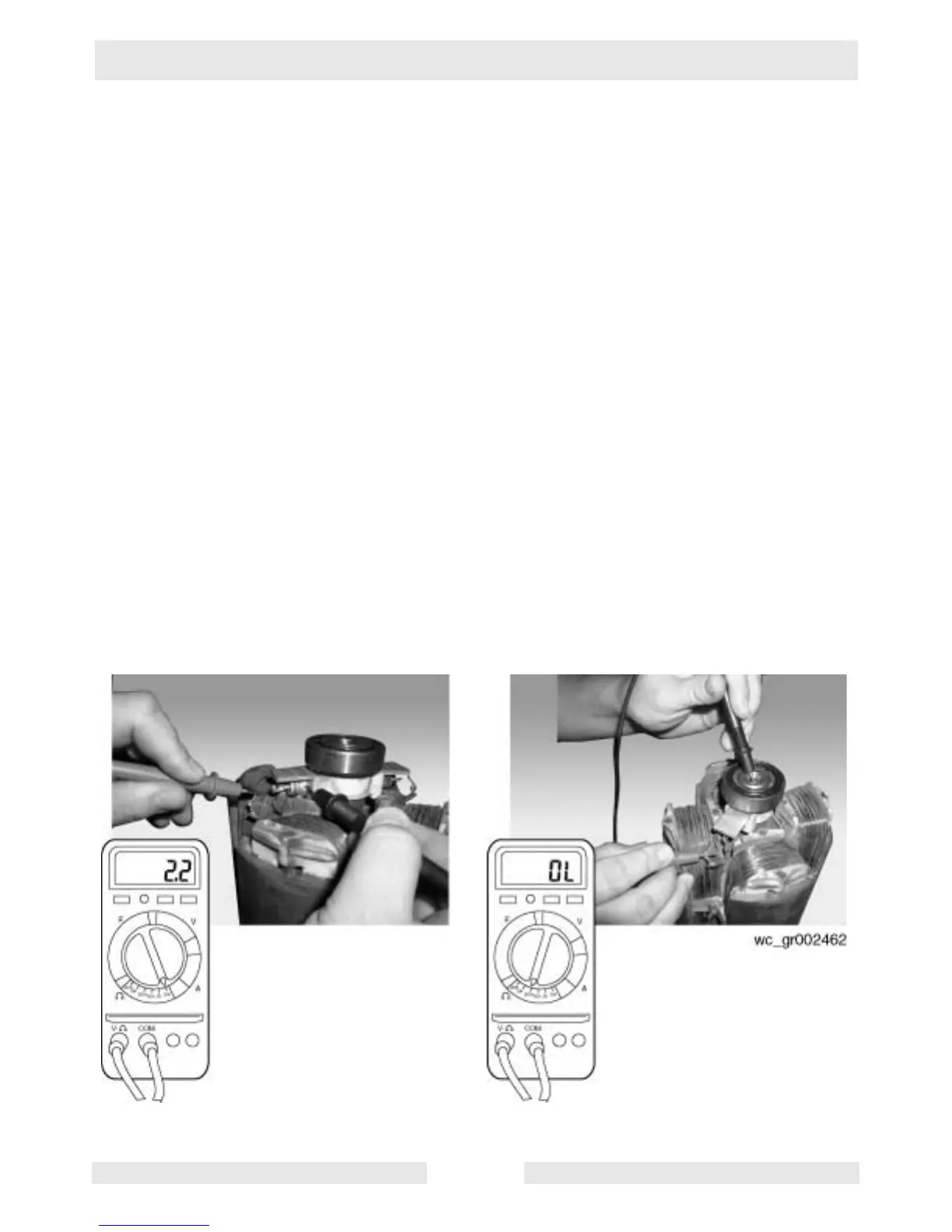
7.34 Checking Rotor Windings
See Graphic: wc_gr002462
After checking the two rotor diodes, check the rotor windings. The
engine/generator assembly must be removed and the stator must be
separated from the rotor to check the rotor windings.
7.34.1 Unsolder the two rotor winding wires from the terminal end of each
diode.
7.34.2 Using the Ohms setting on the multimeter, measure the resistance
across the wires and the base of the corresponding diode. Each wire
reading should be 2.2+0.5/-0.0 Ohms or greater. If your readings are
not 2.2+0.5/-0.0 Ohms or greater, replace the generator.
7.34.3 Check the resistance of all four rotor windings in this manner.
7.34.4 Also check the resistance across the wires and the rotor shaft. If your
readings are not OL, or greater than 2 megohms (2M Ohms), replace
the generator. Confirm with factory before replacing.
7.34.5 Check all four wires in this manner.
For a more thorough insulation test, use a megger meter capable of
500 Volts or have a motor repair shop test it. If readings are 2
megohms (2M Ohms) or greater, rotor is good. If readings are less
than 2 megohms, replace the generator end. Consult factory to
confirm.