Electrical Troubleshooting Procedures LTC Repair
wc_tx000429gb.fm 90
7. Electrical Troubleshooting Procedures
7.1 Troubleshooting Methodology
See Graphic: wc_gr002459
If a lighting problem is not an obvious burnt bulb, engine speed, or wire
fault, the cause of the problem will be associated with one of two
things: a malfunctioning generator or faults in the circuit supplying
voltage to the lights. By starting the troubleshooting procedures with
the main circuit breaker you can determine whether the problem lies
within the generator or the circuit supplying the lights. Note: You can
quickly determine if the generator is functioning by measuring voltage
at the receptacle. However, if voltage is not measured at the
receptacle, it does not automatically mean the generator is not
functioning - there may be problems with the receptacle. Therefore, it
is best to start troubleshooting at the main circuit breaker.
For troubleshooting a malfunctioning generator, you’ll need to rule out
a demagnetized rotor or problems with: the generator’s capacitors, the
stator windings, the rotor diodes, and finally the rotor windings.
For troubleshooting the lighting circuit, you’ll need to rule out problems
with: the main circuit breaker, the terminal strip, the individual circuit
breakers, the ballast, the control panel capacitors, and the wiring that
connects all the components.
Detailed procedures for making the tests are included in the upcoming
sections of this manual.
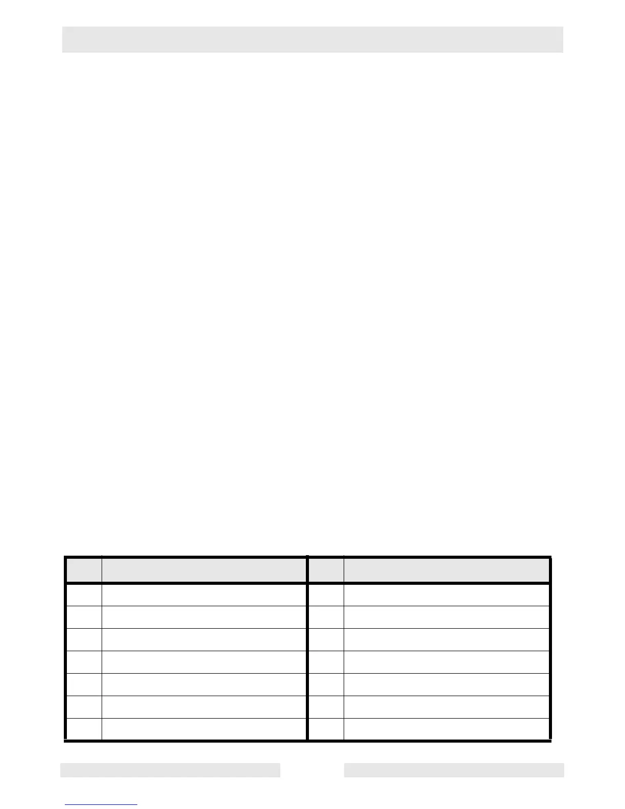
7.2 Schematic Components
See Graphic: wc_gr002459
Ref. Description Ref. Description
a Generator l Transformer
b 20 Amp GFI outlet m Capacitor
c Control box-lights n Ballasts
d Quick disconnects p 25 Amp 2-pole circuit breaker
e Terminal strip q Hourmeter
f 20 Amp GFI circuit breaker r Alternator
g 15 Amp circuit breaker s Control panel