Electrical Troubleshooting Procedures LTC Repair
wc_tx000429gb.fm 126
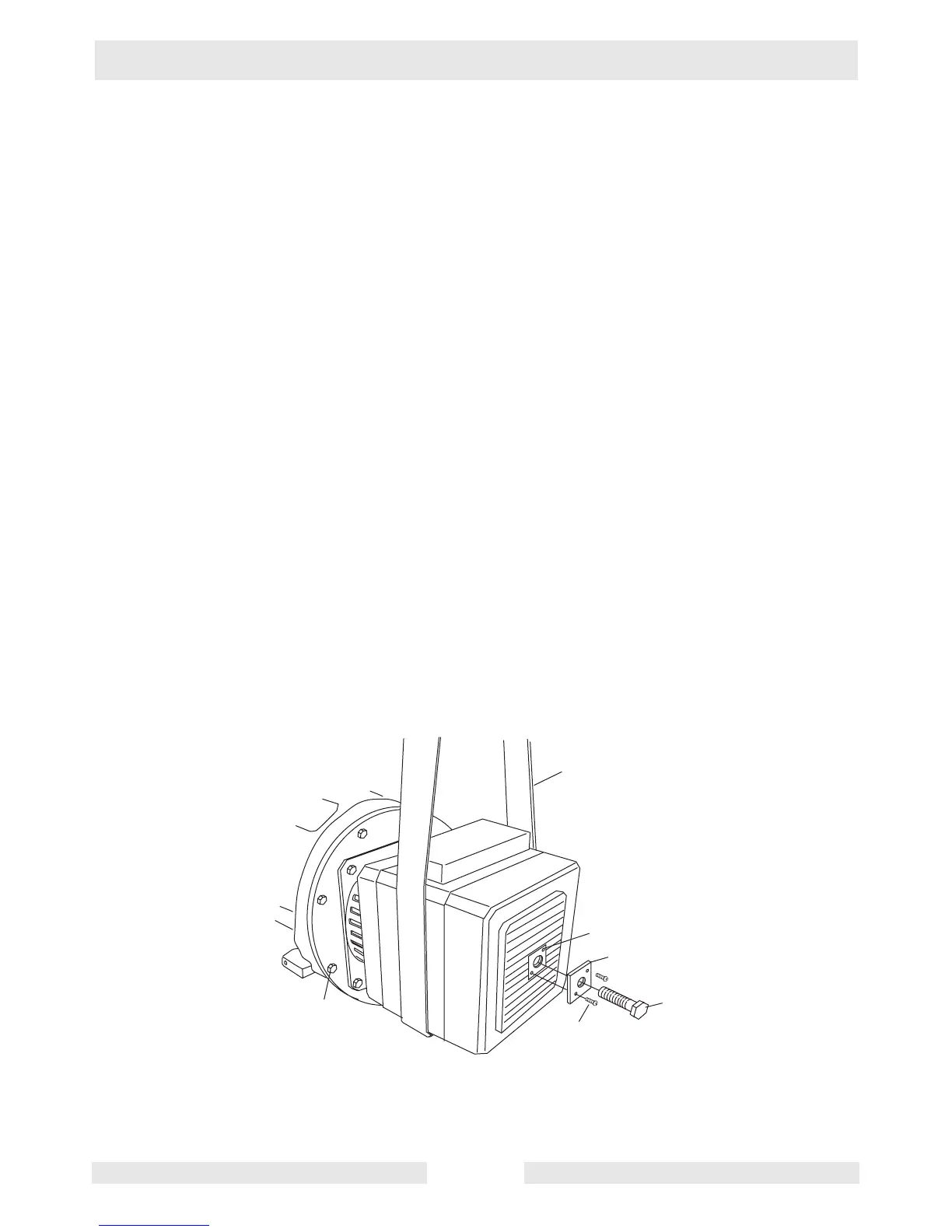
7.31 Separating Stator Assembly from Engine/Rotor Assembly
See Graphic: wc_gr001640
Note: The fit between the rotor bearing and the stator housing is tight.
The tight fit prevents the bearing from spinning in the housing.
7.31.1 There are two methods to separate the stator assembly from the
engine/rotor assembly. The first method involves creating a special
pusher tool. When using either method, support the stator assembly
with an appropriate strap and hoist.
Method 1
7.31.2 Using an appropriate strap (a) and hoist, support the generator end.
7.31.3 Using an approximately 3" x 3" (8cm x 8cm) piece of steel or aluminum
plate (b), drill a pilot hole in the center of the plate to accommodate an
M14 thread. Tap the hole in the plate with M14 threads.
7.31.4 Drill two holes in the plate whose placement matches those in the
stator housing (f).
7.31.5 Tap the holes (f) in the stator housing and using two screws (c) of the
same thread, secure the 3" x 3" plate to the stator housing.
7.31.6 Remove the M8 bolts (d) securing the engine adapter flange to the
engine.
7.31.7 Using an M14 bolt (e), thread it into the M14 threaded hole of the plate
and slowly pull the stator assembly from the engine/rotor assembly.