LTC Repair Electrical Troubleshooting
wc_tx000429gb.fm 95
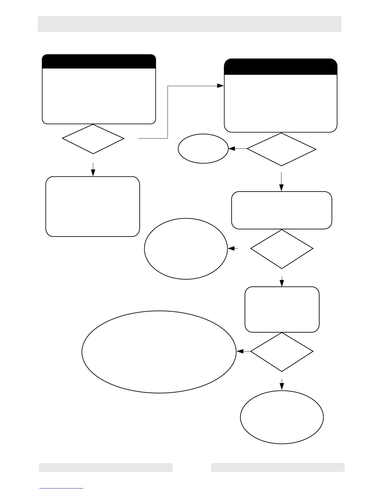
7.10 Lights do not Illuminate—Flowchart 1C
Checking stator windings.
With engine shut down, remove red,
white, and black wires from the
terminal strip on the generator.
Measure resistance across terminals
T1 to T2: 0.36 +0.5/-0.0 Ohms
T4 to T5: 0.36 +0.5/-0.0 Ohms
#0 to #60: 1.7 +0.5/-0.0 Ohms
Restoring Rotor Magnetism (Flashing)
Remagnetize (flash) the rotor windings
by connecting a 12V battery to
capacitor leads #60 and #0.
Start the engine and check
voltage at generator terminal strip:
T1 (red) to T2 (white);
and T5 (black) to T2 (white).
wc_gr003094
No
Ye s
Ye s
Ye s
No
With engine shut down
Check continuity across terminals:
T1 to ground; T5 to ground.
No
Replace stator.
Consult factory.
Is 30–40V
measured?
Are all
resistance values
within range?
No
Ye s
If you measure low
resistance, there is a
short. Replace the
complete generator end.
Consult factory.
For a thorough check of winding insulation,
use a megger meter at 500V or have it tested
by a motor repair shop. If after testing more than
2 M Ohms is not measured, replace the stator.
Consult factory. If continuity tests are OK,
stator is good. Check rotor and diodes.
See Flowchart 1D.
Does meter
read "OPEN"
or "OL"?
Does meter
read "OPEN"
or "OL"?
If you measure low
resistance, there is a
short. Replace the
complete generator end.
Consult factory.
Stop the engine.
Reconnect the #60 and #0
leads to the capacitor.
Start the machine and check
voltage at 120V receptacle. If
120V is not measured, check
generator capacitors.
With engine shut down,
check continuity across:
#60 wire to ground;
#60 wire to T1;
#60 wire to T5.