Performing 600 Controller Extended Test Routines 97
Table 5-3 summarizes the 600 controller test routines.
If any tests fail during this procedure, notify Waters Technical Service.
Required Tools
Tools required for the extended test routines are:
• Jumper wire to short various 600 controller rear panel terminals (Figure 5-2) to a
ground screw terminal
Note: Use a jumper wire that is a 6 to 8-inch (152 to 203 mm) length of insulated
wire (16-18 AWG). Strip the insulation 3/4 inch (19 mm) from each end.
• Screwdriver
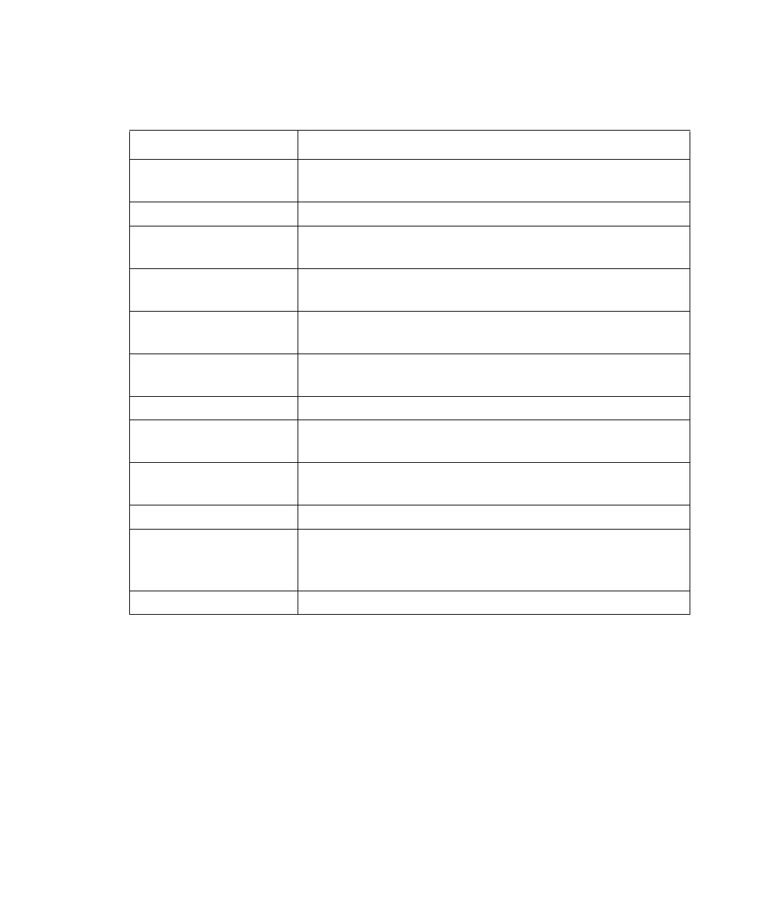
Table 5-3 600 Controller Extended Test Routines
Test Description
Keyboard test Tests the keys on the front panel of the 600 controller. The
LCD displays an echo of the key as it is pressed.
Stop Flow test Tests the Stop Flow input terminal on the rear panel.
External Inject test Tests the Inject input terminal on the 600 controller rear
panel.
External switch test Tests each switch terminal (S1 through S4) on the 600
controller rear panel.
Hold switch test Tests the Hold output terminal on the 600 controller rear
panel.
Chart test Generates a 0 to 10 mV sawtooth waveform at the Chart
terminals on the 600 controller rear panel.
Sparge valve test Turns each sparge valve on and off in sequence.
Pump and proportioning
valve test
Sets the pump to a low flow rate and switches the propor-
tioning valve periodically.
IEEE-488 address test CPU reads and displays the setting of the 600 controller
IEEE-488 address.
RS-232 test Tests the RS-232 communication interface.
12 V fail test Operates the valves at a very fast rate causing 12 V power to
be applied continuously to the valves. If this condition is
detected, the test passes.
Counter test Verifies that the valves cannot switch to a 50/50 condition.
 Loading...