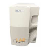
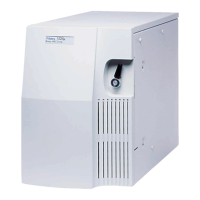
Maintaining 600E Pump Components 61
4.2.2 Calibrating and Replacing the Pressure Transducer
Calibrating the Transducer
Proper pump calibration ensures accurate operation.
1. Disconnect the transducer outlet from the system.
2. Remove the pump cover.
3. Power on the controller.
4. Access the Isocratic or Direct Control screen (depending on your controller
configuration).
5. On the screen, set flow rate to 0.0 mL/min. Verify that flow rate is approximately
0.0 mL/min. If necessary, use the transducer zero adjust screw on the front of the
pump (Figure 4-2) to adjust the pressure until the display on the screen reads zero.
Vent holes (top of
flange)
Provide access for flushing residue from the backs of the
plungers (positions on right head shown).
Reference valve Assists pump priming. Used with detectors requiring refer-
ence solvent stream.
Pressure filter Smooths minor flow fluctuations and enhances solvent
mixing during multi-solvent operation.
Accumulator Performs a similar function to the pressure filter, but with a
larger volume capacity. To use, disconnect the fittings for the
pressure filter and substitute the fittings for the accumulator.
Pressure transducer Senses backpressure developed by resistance to solvent
flow.
Pump outlet Outlet for solvent flow to column or similar device, such as
a switching valve.
Rheodyne 7725i Manual
Injector (optional)
Manual sample injector.
STOP
Attention: Always open the reference valve to relieve system pressure
when performing calibration.
Table 4-1 600E Pump Assemblies (Continued)
Description Function