36 Making Electrical Connections to the 600 Controller
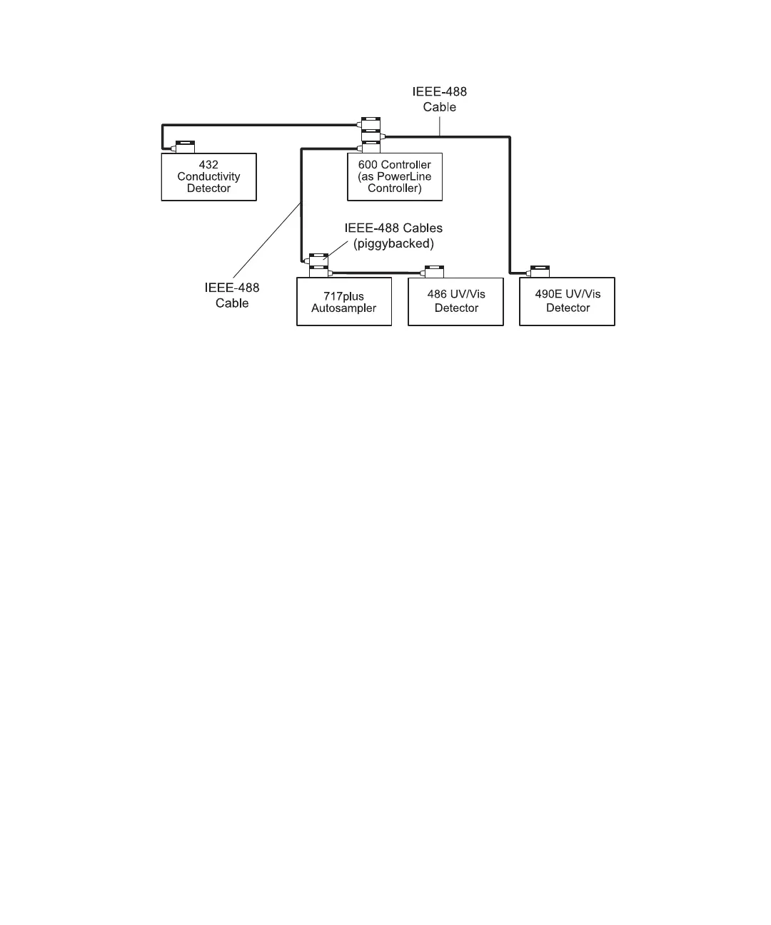
Figure 3-5 PowerLine Controller IEEE-488 Connections
4. Repeat steps 2 and 3 for additional PowerLine components.
Note: The maximum total cable length between IEEE-488 devices is 65 feet (20
meters). The maximum recommended cable length between two IEEE-488 devices
is 13 feet (4 meters). Longer total cable lengths can cause intermittent IEEE-488
communication failures.
5. Ensure that all IEEE-488 cable screws are fastened finger-tight.
6. Set a unique IEEE-488 address between 2 and 29 for each PowerLine device
connected on the IEEE-488 bus (see Section 3.3.3, Setting IEEE-488 Addresses).
Note: Perform the correct IEEE-488 powerup sequence for the PowerLine system
as described in Section 3.3.4, Performing IEEE-488 Powerup Sequence.
Attaching a Waters 432 Detector to a PowerLine System
In the PowerLine mode, the 600 PowerLine Controller supports operation with a Waters
432 conductivity detector through an interface box. You must use the interface box to
communicate with the 432 detector over the IEEE-488 interface. When operating with the
Waters 432 conductivity detector, the 600 PowerLine Controller supports operation
directly over the IEEE-488 interface (as illustrated in Figure 3-5).
1. Connect the IEEE-488 cable (stackable connector for daisy-chaining additional
instruments) from the 600 controller to the IEEE-488 connector on the interface box
(Figure 3-6).