November 16, 2016, 715004521 Rev. C
Page 26
2.3.2 Equilibrating the system
Equilibrating the system involves setting the conditions for the method you plan to run for your
analysis. For example, setting the flow rate, solvent composition, column temperature, ABPR
pressure and other such conditions.
See: The ACQUITY UPC
2
Binary Solvent Manager Operator’s Overview and Maintenance Guide
for details about priming and equilibrating the system. Also see the ACQUITY online Help.
2.4 Observing the sample-injection sequence
The following diagrams illustrate the sample set up and injection sequence in an ACQUITY UPC
2
system.
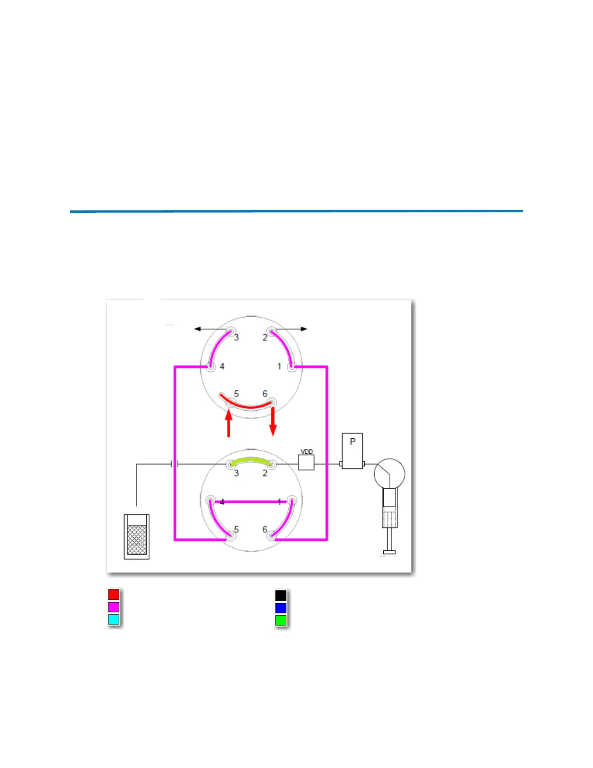
Figure 2–3: Step 1: SM-FL runs internal setup tests and decompresses the sample
loop
At the start of an injection, the injection valve is in the “inject” position (from the previous injection).
The SM-FL signals the auxiliary valve to turn 60° to the “load” position, to enable the connecting
tubes from the two valves to vent to atmosphere (including the sample loop on the injection valve).
Waste
Waste
Auxiliary valve (load position)
Metering syringe
Injection valve (inject position)
Sample
Liquid mobile phase (CO
2
)
Gas mobile phase (CO
2
)
Air gap
Buffer volume
Sample
Weak wash
From pump
To col umn
Sample loop