November 16, 2016, 715004521 Rev. C
Page 42
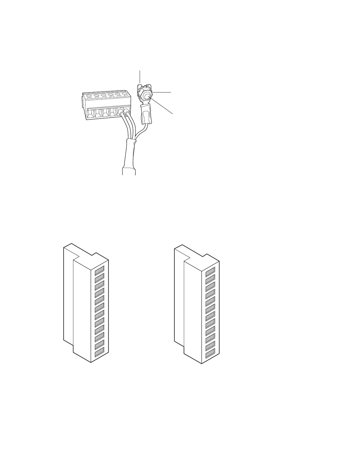
Tip: Use the 9/32-inch nut driver to tighten the locking nut until the fork terminal does not
move.
4.2.1.1 Connecting the ccBSM I/O signal cables
The rear panel of the ccBSM includes two removable connectors that hold the screw terminals for
I/O signal cables. These connectors are keyed so that they can be inserted only one way.
Figure 4–2: ccBSM analog-out/event-in signal connectors
Fork
terminal
Locking nut
Grounding
stud
Connector I
Connector II
1
2
3
4
5
6
7
8
9
10
11
12
+
−
+
−
+
−
Auxiliary 1 In
Auxiliary 1 In
Auxiliary 2 In
Auxiliary 2 In
Ground
Run Stopped Out
Run Stopped Out
Switch 1 Out
Switch 1 Out
Ground
0-2V Analog 1 Out
0-2V Analog 1 Out
1
2
3
4
5
6
7
8
9
10
11
12
+
−
+
−
+
−
Start Gradient In
Start Gradient In
Stop Flow
Stop Flow
Ground
Switch 2 Out
Switch 2 Out
Switch 3 Out
Switch 3 Out
Ground
0-2V Analog 2 Out
0-2V Analog 2 Out