November 16, 2016, 715004521 Rev. C
Page 43
For electrical specifications, see the ACQUITY UPC
2
System Specifications Guide.
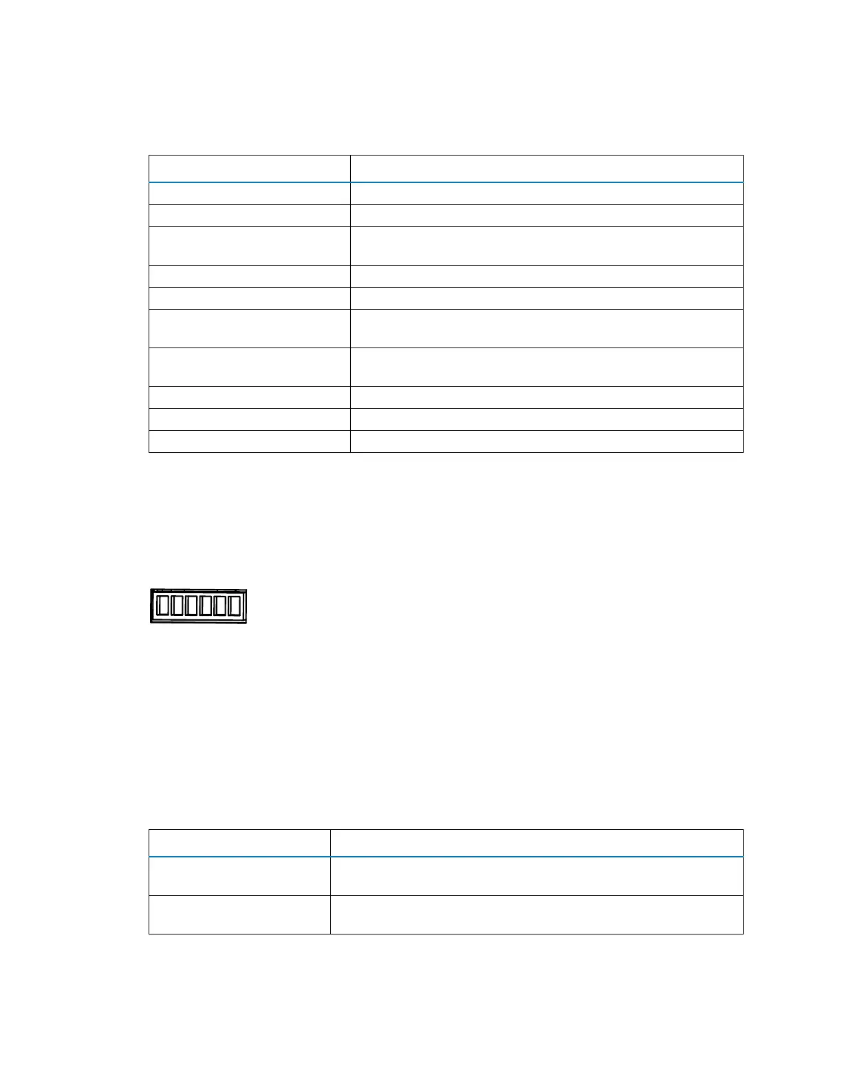
4.2.1.2 Connecting the SM-FL I/O signal cables
The rear panel of the SM-FL includes a removable connector that holds the screw terminals for I/O
signal cables. This connector is keyed so that you can insert a signal cable only one way.
Figure 4–3: SM-FL I/O signal connectors
For electrical specifications, see the ACQUITY UPC
2
System Specifications Guide.
Table 4–1: ccBSM analog-out/event-in connections
Signal connection Description
Auxiliary 1 In Reserved for future use.
Auxiliary 2 In Reserved for future use.
Run Stopped Out Indicates (with a contact closure) the ccBSM stopped operating
because of an error condition or operator request.
Switch 1 Out Reserved for future use.
0−2V Analog 1 Out Reserved for future use.
Gradient In Initiates the pumps to begin gradient operation by contact
closure input or 0-volt input.
Stop Flow In Stops the flow from the ccBSM when an error condition or
hardware failure occurs on another system module.
Switch 2 Out Reserved for future use.
Switch 3 Out Reserved for future use.
0−2V Analog 2 Out Reserved for future use.
Table 4–2: SM-FL event-out/event-in connections
Signal connections Description
Inject Start Out Indicates (with a contact closure output) that an injection has
started.
Inject Hold In Delays the next injection when the SM-FL receives a contact
closure input (from another system module, for example).
12 3 4 5 6
Inject Start Out +
Inject Start Out -
Ground
Ground
Inject Hold In +
Inject Hold In -