Table
2-6.
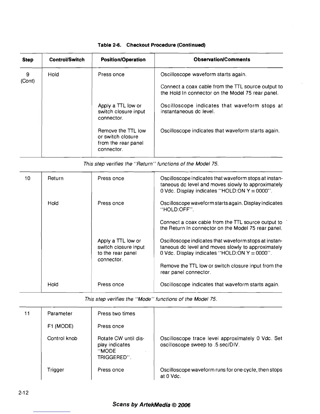
Checkout Procedure (Continued)
9
(Cont)
Hold
Step
Press once
ControllSwitch
PositionlOperation
Apply a 7TL low or
switch closure input
connector.
ObservationlComments
Remove the 7TL low
or switch closure
from the rear panel
connector.
Oscilloscope waveform starts again.
Connect a coax cable from the
7TL source output to
the Hold In connector on the Model
75
rear panel.
Oscilloscope indicates that waveform stops at
instantaneous dc level.
Oscilloscope indicates that waveform starts again.
Return
Hold
This step verifies the "Return" functions of the Model
75.
Press once
Press once
Apply a
7TL low or
switch closure input
to the rear panel
connector.
Oscilloscope indicates that waveform stops at instan-
taneous dc level and moves slowly to approximately
0
Vdc. Display indicates "H0LD:ON
Y
=
0000".
OsciIloscope waveform starts again. Display indicates
"HOLD:OFFM.
Connect a coax cable from the TrL source output to
the Return In connector on the Model
75
rear panel.
Oscilloscope indicates that waveform stops at instan-
taneous dc level and moves slowly to approximately
0
Vdc. Display indicates "H0LD:ON
Y
=
0000".
Remove the 7TL low or switch closure input from the
rear panel connector.
I
Hold press once Oscilloscope indicates that waveform starts again.
This step verifies the "Mode" functions of the Model
75.
I
Parameter
F1
(MODE)
Control knob
Trigger
Press two times
Press once
Rotate CW until dis-
play indicates
"MODE
TRIGGERED".
Press once
Oscilloscope trace level approximately
0
Vdc. Set
oscilloscope sweep to
.5
seclDIV.
Oscilloscope waveform runs for one cycle, then stops
at
0
Vdc.
Scans
by
ArtekMedia
O
2006