Table
2-6.
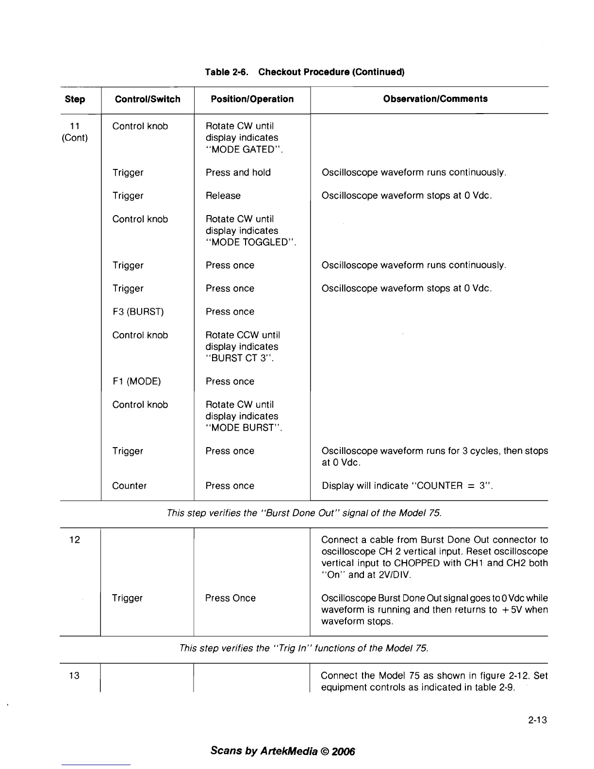
Checkout Procedure (Continued)
This step verifies the "Burst Done Out" signal of the Model 75.
0
bservationlComments
Oscilloscope waveform runs continuously.
Oscilloscope waveform stops at
0 Vdc.
Oscilloscope waveform runs continuously.
Oscilloscope waveform stops at
0 Vdc.
Oscilloscope waveform runs for 3 cycles, then stops
at
0 Vdc.
Display will indicate "COLINTER
=
3".
This step verifies the "Trig In" functions of the Model 75.
PositionlOperation
Rotate CW until
display indicates
"MODE GATED".
Press and hold
Release
Rotate CW until
display indicates
"MODE TOGGLED".
Press once
Press once
Press once
Rotate CCW until
display indicates
"BURST CT
3".
Press once
Rotate CW until
display indicates
"MODE BURST".
Press once
Press once
Step
11
(Cont)
12
Connect the Model 75 as shown in figure 2-12. Set
equipment controls as indicated in table
2-9.
ControllSwitch
Control knob
Trigger
Trigger
Control knob
Trigger
Trigger
F3 (BLIRST)
Control knob
F1 (MODE)
Control knob
Trigger
Counter
Scans
by
Artekhledia
O
2006
Trigger Press Once
Connect a cable from Burst Done Out connector to
oscilloscope CH 2 vertical input. Reset oscilloscope
vertical input to CHOPPED with
CHI and CH2 both
"On" and at
2VIDIV.
Oscilloscope Burst Done Out signal goes to OVdc while
waveform is running and then returns to
+
5V when
waveform stops.