Figure 2-1
3.
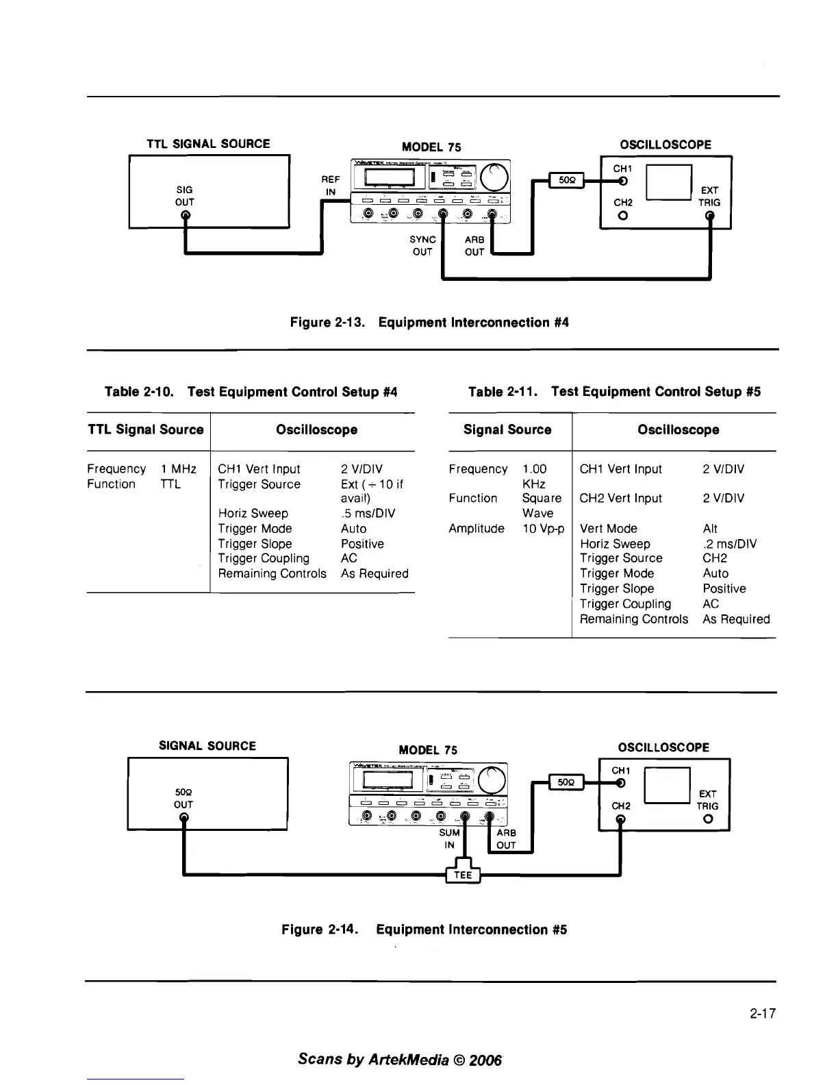
Equipment lnterconnection #4
TTL SIGNAL SOURCE
MODEL 75 OSCILLOSCOPE
SIG
OUT
Q
Table 2-10. Test Equipment Control Setup #4 Table 2-1 1. Test Equipment Control Setup #5
Frequency 1 .OO
KHz
Function Square
Wave
Amplitude 1 0 Vp-p
REF
IN
-
TTL Signal Source
Frequency 1 MHz
Function
lTL
Signal Source
CHI Vert Input 2 VIDIV
SYNC
OUT
Oscilloscope
CHI Vert Input 2 VIDIV
Trigger Source Ext (-10 if
avail)
Horiz Sweep
.5
ms1DIV
Trigger Mode
Auto
Trigger Slope
Positive
Trigger Coupling AC
Remaining Controls As Required
Oscilloscope
CH2 Vert Input 2 VIDIV
'rn-mo'
0
0
.
-
-
...
.
OOOOOOOO0
@
L@
@
69
@
..q
ARB
OUT
Vert Mode Alt
Horiz Sweep
.2 ms1DIV
Trigger Source CH2
Trigger Mode Auto
Trigger Slope Positive
Trigger Coupling AC
Remaining Controls As Required
50Q
cl
CH2
,;
-
0
Q
SIGNAL SOURCE MODEL 75 OSCILLOSCOPE
CH2
0
SUM
ARB
IN
OUT
Figure 2-14. Equipment lnterconnection #5
Scans
by
ArtekMedia
O
2006