Chapter 3: Installing Power, Surge Protection, and Communications
•
25
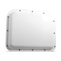
Figure 20. Attaching the pole-mount box
1 Find the mounting brackets that were included in the pack-
age and attach them to the back of the Surge Preassembled
Cabinet.
2 Use Band-It or a similar clamping system to attach the Surge
Preassembled Cabinet to the pole.
Lightning
Surge
Protection
W
ProtectedProtected
Click!
200
RS-485RS-232 DCE
To SmartSensor
GNDGNDRDTDCTSRTSGND
485+485-GND-DC+DC
To Trac Cabinet
GNDGNDRDTDCTSRTSGND
485+485-GND-DC+DC
GNDGNDRDTDCTSRTSGND485+485-GND-DC+DC
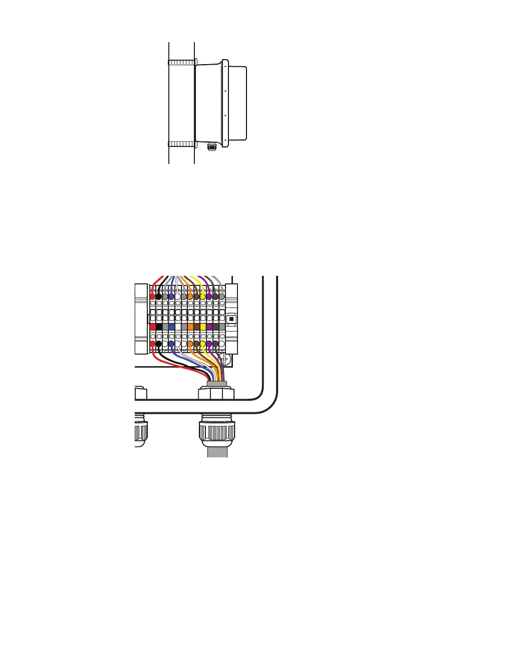
Figure 21. Connecting sensor cable to terminal blocks
3 Insert the sensor cable (the pigtail cable coming from the
sensor) through the rightmost cable grip on the bottom of the
box. Twist the cable grip to tighten.
4 Start connecting conductors to the terminal blocks marked “To
SmartSensor”: insert the red conductor into the round hole on
the plug portion of the +DC terminal block (do not strip the insu-
lation). Insert a small screwdriver into the square hole above it,
and rock upwards to secure the conductor in place.
5 Repeat step 4 to land each conductor into the correct terminal