Wecon VD2 SA Series Servo Drives Manual (Lite V1.1)
WECON technology Co., Ltd
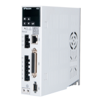
Table 4-7 Absolute value encoder line connector (Rectangular plug)
Rectangular plug
pin number
Serial communication signal +
Serial communication signal -
Table 4-8 Connection of encoder line pin
The pin with “*” indicates the signal line of encoder battery. If the multi-turn battery memory
function is not used, you don’t need to connect the signal lines. It is only used as single turn
encoder line at this time.
✎ Note: The color of the line is subject to the actual product. The lines described in this manual are
all lines of Wecon!
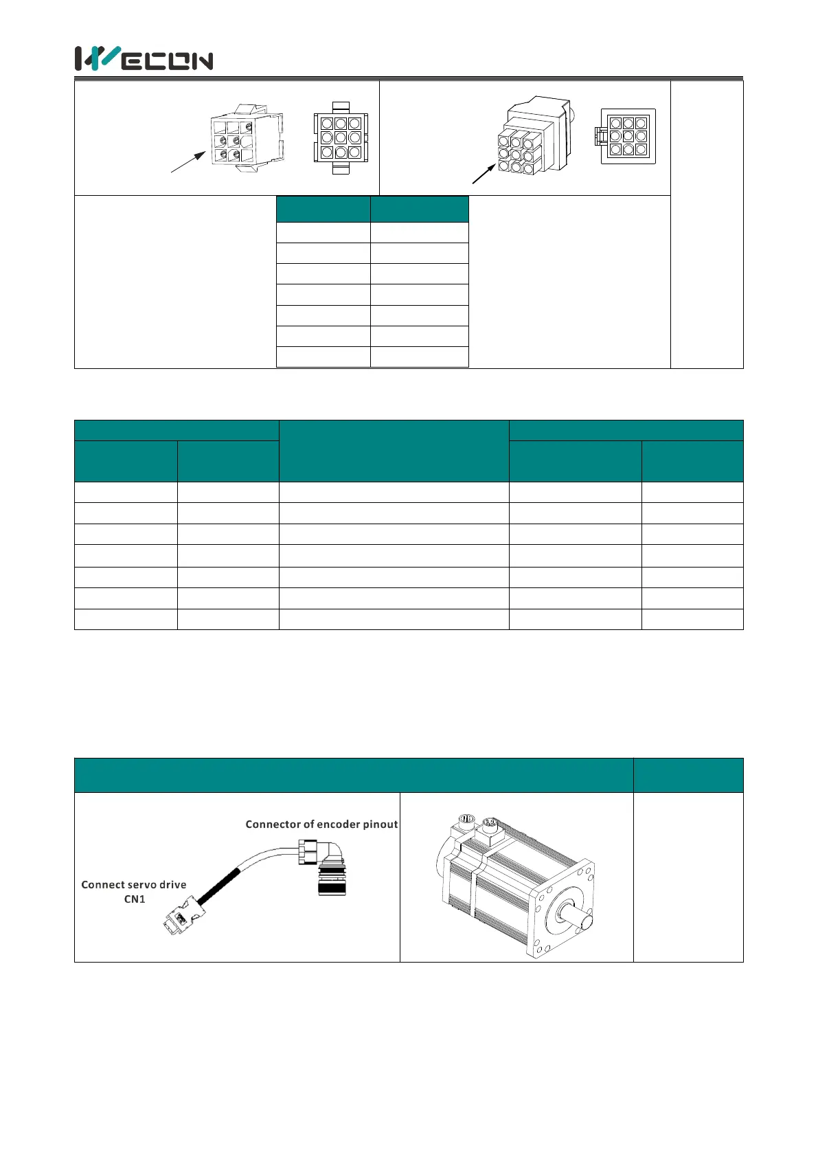
Connector shape and terminal pin distribution
E nc o de r c o nn e cte d to a s o ck et
 Loading...