59
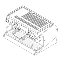
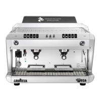
Wegaconcept
Technical manual
ENGLISH
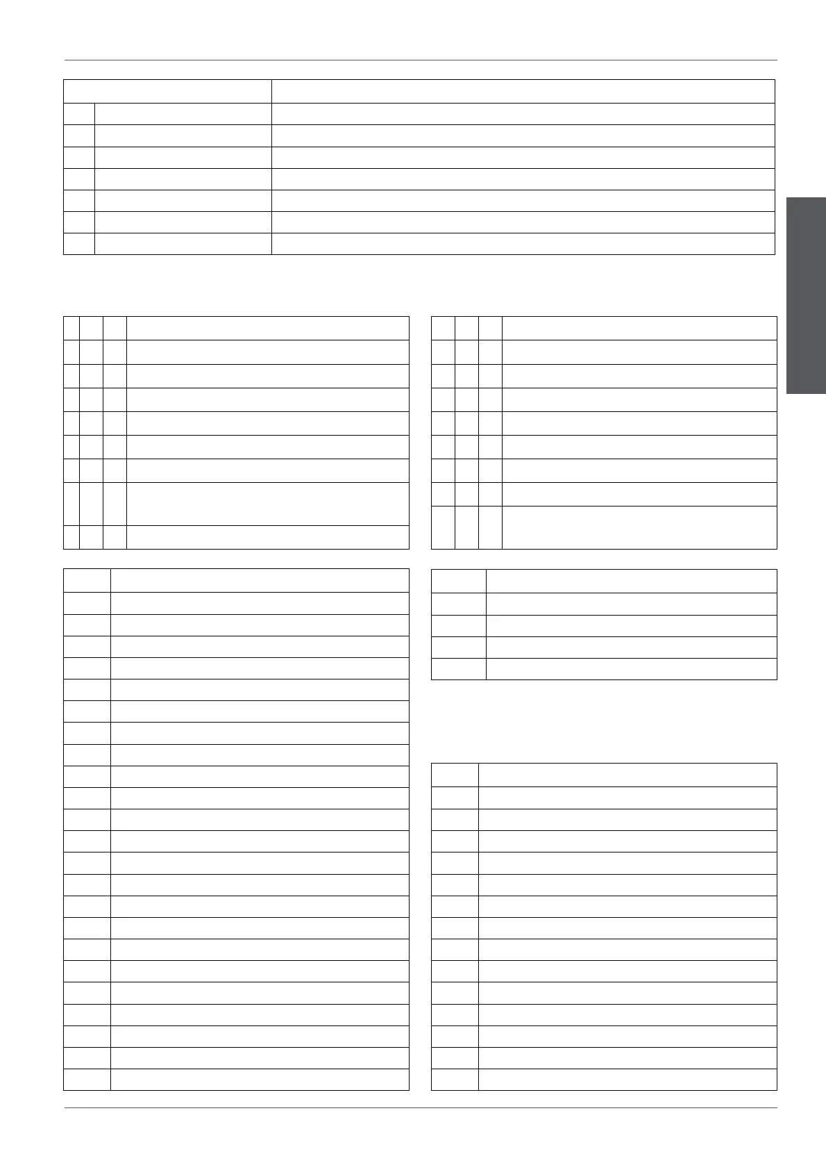
Fuse Description
F1 Fuse 5x20 delayed by 6.3A Protects: from RL1 to RL14
F2 Fuse 5x20 delayed by 12.5A Protects: coee boiler heating element group 2 and 4
F3 Fuse 5x20 delayed by 12.5A Protects: coee boiler heating element group 1 and 3
F4 Fuse 5x20 delayed by 1A Protects: transformer's double winding
F5 Fuse 5x20 super rapid 12.5A Protects : group heating elements 1 and 3
F6 Fuse 5x20 super rapid 12.5A Protects : group heating elements 2 and 4
F7 Fuse 5x20 delayed by 1A Protects: services boiler heating elements 1 and 2
LED Description
DL1 Cup heater
DL2 +5V
DL3 +9V
DL4 Heating element control boiler group 4
DL5 Heating element control boiler group 2
DL6 Heating element control boiler group 3
DL7 Heating element control boiler group 1
DL8 group 1 heating element
DL9 +5V
DL10 +9VB
DL11 group 3 heating element
DL12 +9VA
DL13 group 2 heating element
DL14 group 4 heating element
DL15 group 4 volumetric counter
DL16 group 3 volumetric counter
DL17 group 2 volumetric counter
DL18 group 1 volumetric counter
DL19 services 1 boiler heating element
DL20 +12V pressure gauge
DL21 services 2 boiler heating element
+VAL-T transducer's power supply to +VAL
+5V-T transducer's power supply to +5V
Relay Description
RL1 Pump
RL2 Solenoid valve group 1
RL3 Solenoid valve group 3
RL4 Solenoid valve group 2
RL5 Solenoid valve group 4
RL6 Boiler lling solenoid valve
RL7 Hot water mix solenoid valve
RL8 Tea solenoid valve
RL9 Autosteamer steam solenoid valve
RL10 Cup heater
RL11 Aux. solenoid valve
RL12 Air solenoid valve
RL13 Tea solenoid valve 2
RL14 Aux
Jumper Description
JP2 Not managed
JP4 Aux
JP13 TX-RX signal inversion
JP19 TX-RX signal inversion
O On SW1 Switch
1
JF
Not used. leave on OFF mode.
2
JF
Reserve.
3
JF
Reserve.
4
JF
Reserve.
5
JF
Reserve.
6
JF
ON = rinse active for 3 secs. PROG./STOP key.
7
JF
ON = excludes the automatic control of the services boiler
temperature.
8
JF
ON = Pre-infusion active
O On SW2 Switch
9
JF
ON = 6 doses keyboard.
10
JF
ON = rinse active for 3 secs. dose keys
11
JF
ON = Active Credit / Debit.
12
JF
ON = Reset machine life cycle
13
JF
ON = Continuous disabled.
14
JF
ON = NTC probe
15
JF
ON = Serial communication active.
16
JF
ON = MICRO-Processor programming.
OFF = Machine service enabled