63
Wegaconcept
Technical manual
ENGLISH
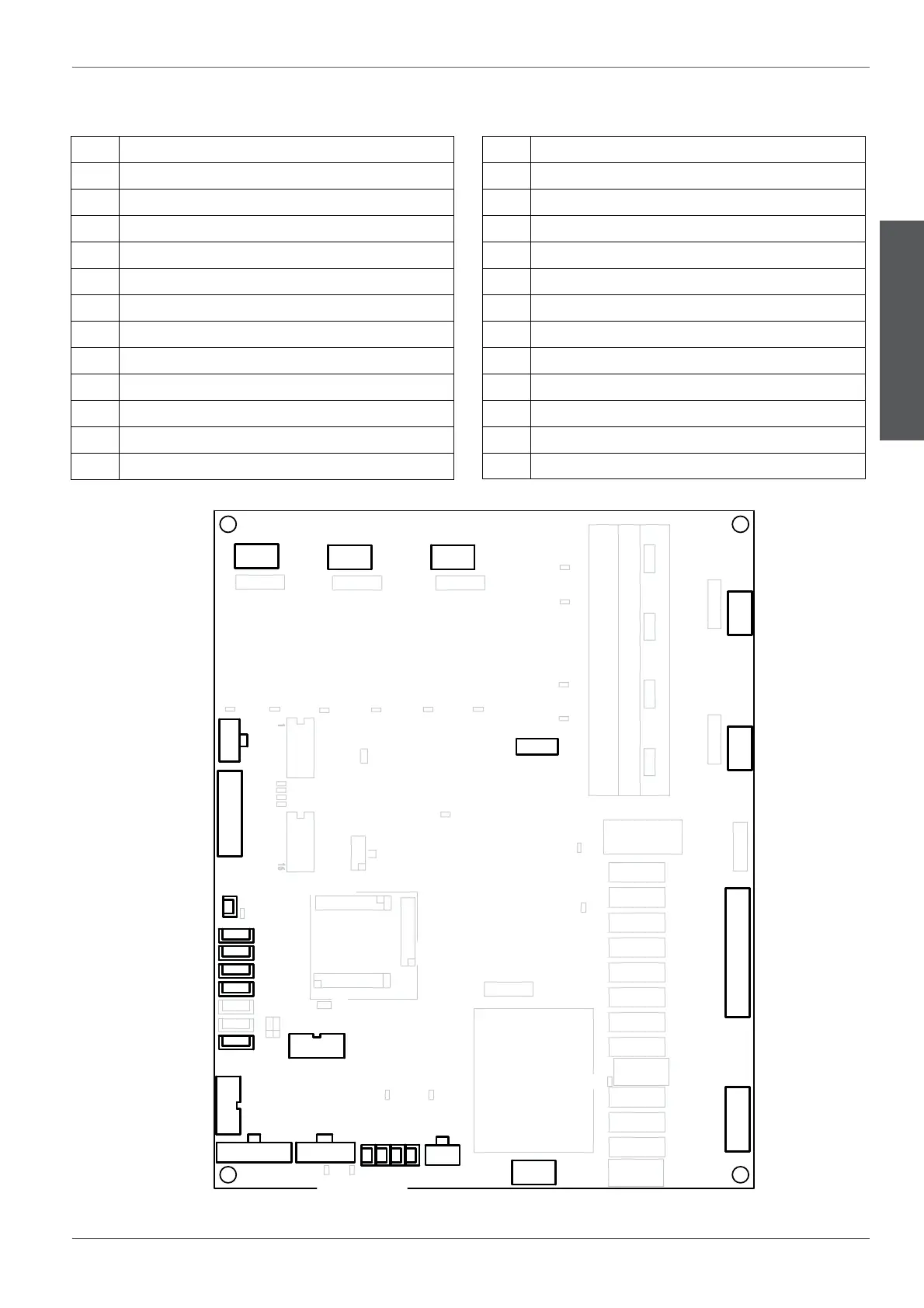
33.4 Connectors electric diagram
02.46.0136 r0
DL10DL12
DL3
DL9
DL8DL11
DL18
DL13
DL17
DL16
DL15
DL14DL19DL21
DL20
DL2
DL4
DL5
DL6
DL7
DL1
+5V-T
+VAL-T
CN13
CN5
CN8
CN9
CN10
CN21
CN16CN15
CN4
CN24 CN23
CN25CN26
CN1
CN3
CN2
CN22
CN28
CN6
CN11
CN12
CN27
CN14
CN7
CN17
CN18
CN19
CN20
RL3
RL14
RL4
RL1
RL5
RL11
RL10
RL12
RL2
RL8
RL13
RL6
RL7
RL9
JP2
JP3
JP19
JP4
F2
F3
F4-T1A
F5F6
F7
F1
PRG
TRF1
TR4TR3TR2TR1
J1
J2
J3
J4
J5
SW1
SW2
CN1 Connection of groups 1 e 3 heating elements
CN2 Connection of groups 2 e 4 heating elements
CN3 Connection of services boiler's heating elements
CN4 Connection of coee boiler pressure switches
CN5 Connection of volumetric dosers and services boiler levels
CN6 Not used.
CN7 Wiring of pressure transducer
CN8 AUX connector
CN9 AUX connector
CN10 AUX connector
CN13 Connection of RS232 serial socket
CN14 Connection of display/CPU
CN15 Connection of NTC temperature sensors
CN16 Connection of coee boiler pressure transducers
CN17 Connection of NTC services boiler
CN18 Connection of NTC autosteamer
CN19 Connection of NTC cup heater
CN20 AUX connector
CN21 Connection of sensor for humidity and mains/pump pressure
CN22 Wiring of circuit board
CN23 Connection of 230V AC outputs
CN24 Connection of 230V AC outputs
CN25 Connection of heating elements for hot water containers 1 and 3
CN26 Connection of heating elements for hot water containers 2 and 4
CN27 Not used.
CN28 Not used.