上海维宏电子科技股份有限公司
Weihong Electronic Technology Co., Ltd.
- 18 - Specialized, Concentrated, Focused
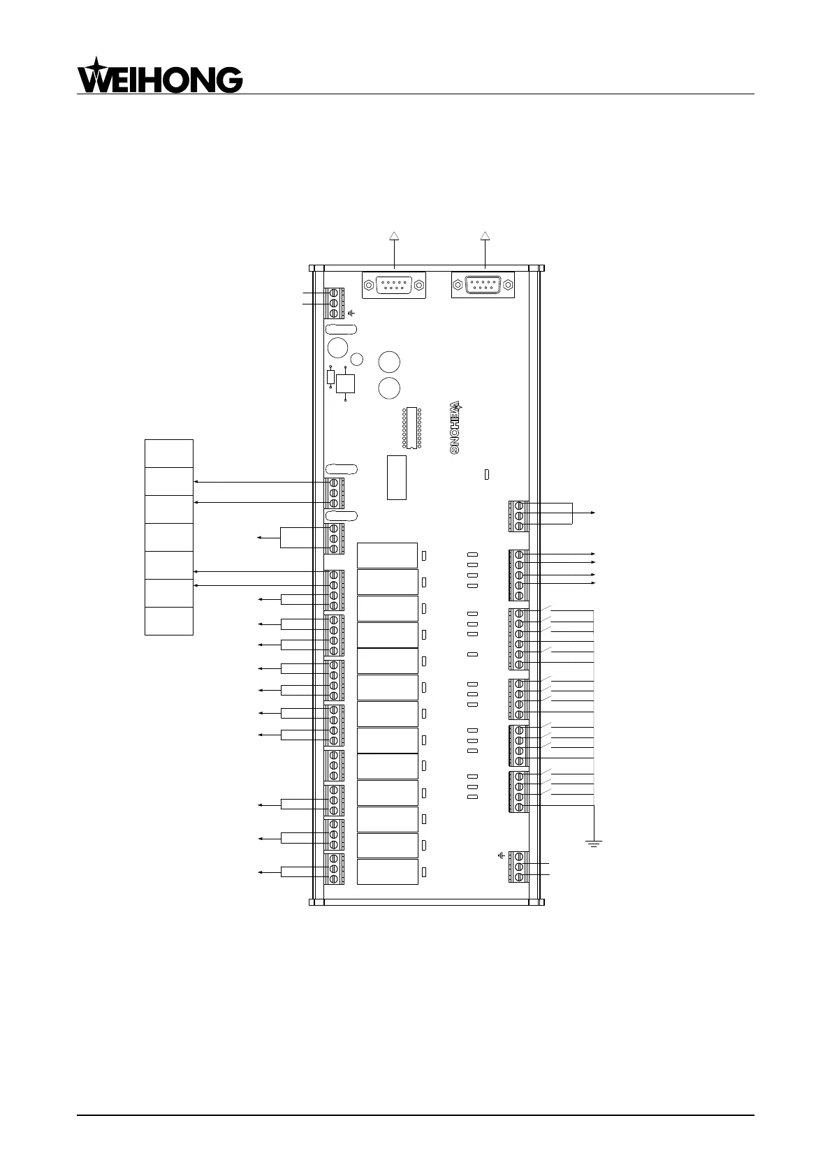
2.2.1 Wiring Diagram of Terminal Board
The wiring diagrams between NK280 and terminal board are shown as follows:
Standard 4-axis system
BRAKE
SVC
GND BRK COM
SPIN
SCOOL
OIL COOL
RED
GREEN
YELLOW
LAMP
NC CONNO NC
CON
NO NC
CON
NO NC CONNO
SPIN SCOOL OIL COOL
RED
GREEN YELLOW
LAMP
GY13 GY12 GY11 GY10
RUN
EX9A4
BRK+ BRK-
GX60
GX59
GX58
GX57
COM
SALAM
OILALM
CUT
COM
W0
COM
ZLIM-
Z0
ZLIM+
COM
YLIM-
Y0
YLIM+
COM
XLIM-
X0
XLIM+
COM
COM
+24V
COM
+24V
SLAVE PORTMASTER PORT
从机接口主机接口
NK280 Host
I/O Interface
-
+
Host Interface of Next
Terminal Board
Z Axis Brake Input
Red
Black
Process Start
Overtravel protection of tool presetter
Spindle Alarm
Oil Level Detection Alarm
Tool calibration signal of Z Axis
REF. Point of A Axis
Negative Limit of Z Axis
REF. Point of Z Axis
Positive Limit of Z Axis
Negative Limit of Y Axis
REF. Point of Y Axis
Positive Limit of Y Axis
Negative Limit of X Axis
REF. Point of X Axis
Positive Limit of X Axis
24VDC
Power Input
-
+
24VDC
Power Input
Analog
Voltage
Analog GND
CW
Digital
GND
Inverter
Terminal
VI
ACM
FOR
DCM
Brake
Output
Spindle Cool
Lube Oil Pump
Workpiece Cool
Red Alarm Light
Green Work Light
Yellow Work Light
Illumination
Tool Magazine CCW
Process Stop
General Input
Tool Magazine CW
Tool Blow
Note: NO ports are normally open while NC ports are normally closed.
Fig. 2-8 Wiring diagram of terminal board EX9A4-standard 4-axis system
 Loading...