上海维宏电子科技股份有限公司
Weihong Electronic Technology Co., Ltd.
- 128 - Specialized, Concentrated, Focused
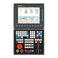
6.1.15 Parameter Setting of KT270 Servo Driver
The control mode of the driver can be set through this
parameter:
0: position control mode; 1: speed control mode;
2: trial run control mode; 3: JOG control mode.
Numerator of
position
command
pulse ratio
Set the ratio of the position command pulse
(electronic gear).
Under position control mode, with the setting of the
PA12 and PA13, it is convenient to match with pulse
source of each type, which can reach users‘ perfect
control resolution (that is angle/pulse)
Expression:
P: pulse amount of the input command;
G: electronic gear ratio, G=ratio numerator / ratio
denominator.
N: circle number that the motor rotates;
C: each circle line number of photo electricity
encoder,
C of our system =2500.
E.G.: input 6000 command pulses to make the servo
motor rotate one circle,
So set PA12 as 5 and PA13 as 3.
We recommend the range of electronic gear ratio as:
Denominator of
the position
command
pulse ratio
Input mode of
the position
command
pulse
Set the input mode of the position command pulse;
there are following three modes can be selected by
setting the parameter:
0: pulse + symbol;
1: positive rotation pulse/ negative rotation pulse;
2: two orthogonal pulses inputs
Default setting is 0: pulse + symbol, negative logic.
Invalid input on
the end of the
stroke
0: Valid stroke end of LSP, LSN positive rotation,
negative rotation.
When switch LSP is connected, driving of the positive
rotation is allowed; When switch LSP is disconnected,
driving of the positive rotation is prohibited (torque of
the positive direction is 0). LSN is the same as LSP. If
LSP and LSN are all disconnected, the abnormal
alarming of driving prohibited will occur (NO.7).
1: Invalid stroke end of LSP, LSN positive rotation,
negative rotation.
No matter which state of the switch LSP and LSN is
in, driving of positive rotation and negative rotation
are all allowed. Simultaneously, even if LSP and LSN
are all disconnected, abnormal alarming of driving
 Loading...