Number of motor lines per module
1x 20A motor line for ±24V standard motors
4 x 10A motor lines for ±24V standard motors
4 x 10A motor lines for MotorLink
®
motors
Note: A total of max 20A current consumption on
each 20A section of the smoke ventilation panel
Metal housing for surface mounting
WSC 520: 380 x 600 x 210mm (WxHxD)
WSC 540: 600 x 600 x 210mm
WSC 560: 1000 x 760 x 210mm
WSC 520: 17kg no batteries, 28kg with batteries (2 x WSA 017)
WSC 540: 26kg no batteries, 49kg with batteries (4 x WSA 017)
WSC 560: 57kg no batteries, 90kg with batteries (6 x WSA 017)
Approved and certified according to EN 12101-10
FlexiSmoke™ smoke ventilation panel with WSA 501 (10kΩ resistors, 10
pcs.); WSC 520 x1, WSC 540 x2, WSC 560 x3 and 1 pcs. end of line
module WSA 510
Back-up batteries to be ordered separately.
Back-up battery WSA 017 (12V/17-18Ah) - order 2 batteries per 20A section
We reserve the right to make technical changes
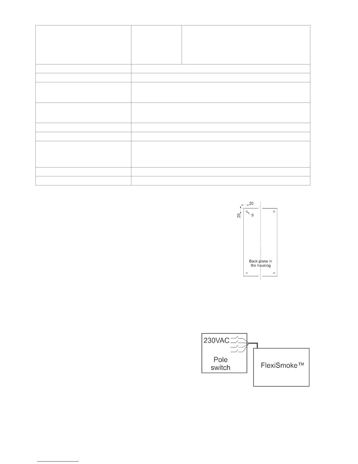
The smoke ventilation panel is fixed to the wall through the Ø9mm holes in the
back plane of the housing.
If the panel is fixed in different way, the holes are to be blinded with the 4 blind
grommets, this way the IP class is maintained.
The door is turnable.
When turning the door also move the blind grommets to the new holes.
The smoke ventilation panel is to be located in a safe place, protected from the
effects of fire and smoke.
7 Installation
7.1 Cable routing
For cable routing we recommend the use of fire protected cables retaining their function E90 or E30.
See also chapter 8 “Cable dimensioning” in this instruction.
However, this has to be agreed with the Engineer or, if necessary, with the local fire protection department.
Do not reduce the cable cross sections specified in the cable lengths table. All cables of the control (except the mains supply
cable) carry 24V DC and have to be routed separate from the mains supply cable.
Adhere to the pertinent national and local regulations when routing
the cables.
Lead the connection cables into the housing of the control panel from
above and the cable glans shall comply with fire class V-1 (IEC/EN
60695-11-20 / UL 94) or higher.
Ensure that the mains cable can be switched via an external or
customer-supplied two-pole switch element or a switch element
controlling all poles – see drawing.
7.2 Cables into housing
All connection terminals (except the mains terminals) are of the plug-in type.
Connect the connection cables in accordance with the terminal plan. Ensure that the connections are made correctly.
Incorrect cable clamping, mixing up numbers or colours could lead to malfunctions of the control panel or of the external
components. Ensure that the electrical cables are always routed according to the valid national and local regulations.