Break glass units are to be configured in:
Configuration of ‘Topology’
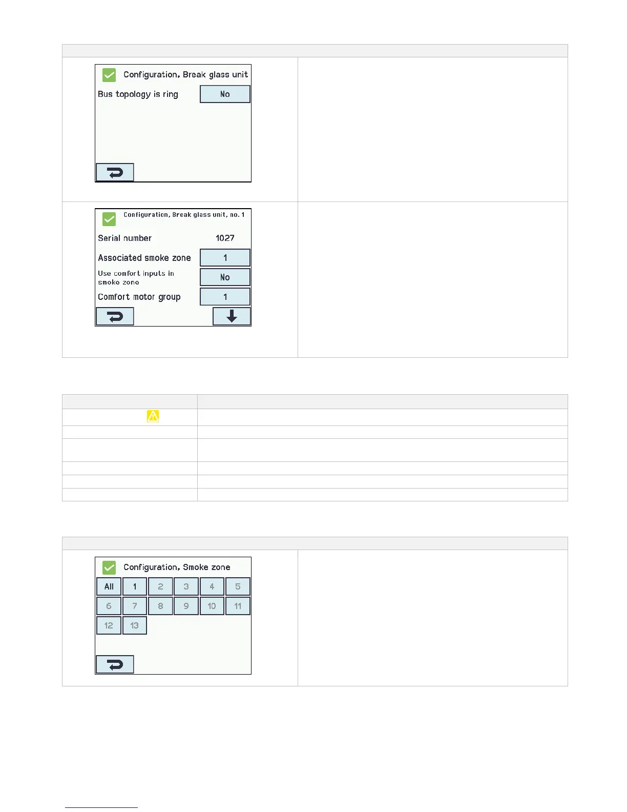
‘All’
1. Bus topology is ring - see text about “Topology” below
The appendix contains all the items that can be configured
- see appendix for detailed explanation.
Configuration of a selected ‘Break glass unit’
- shown for no.1
The numbered break glass units
1. Serial number: the break glass unit’s unique serial no. is
shown (cannot be configured)
2. Associated smoke zone
3. Use comfort inputs in smoke zone
4. Comfort motor group
5. Br.glass unit+sensor same smoke zone
6.1 Smoke sensor associated with smoke zone (displayed
only if ‘Other smoke zone‘ is selected)
6. Unit beep 1min for locating
7. Delete this unit
The appendix contains all the items that can be configured
- see appendix for detailed explanation.
14.4.2 Colour code – break glass unit
The overview fields on the touch screen have colour codes for the break glass units:
The break glass unit are assigned to a smoke zone
The reset-button in the break glass unit is pressed down (used when detecting break
glass unit)
The break glass unit is not assigned to a smoke zone
Configuration is missing or there is a mistake in the configuration
The alarm button in the break glass unit is pressed down (alarm signal)
14.5 Smoke zone
Configuration of master/slave and control zones. Configuration of different opening limits of the windows when alarm is triggered.
Smoke zones configuration