2-4
Chapter 2: Installation and Setup
Aug 2012
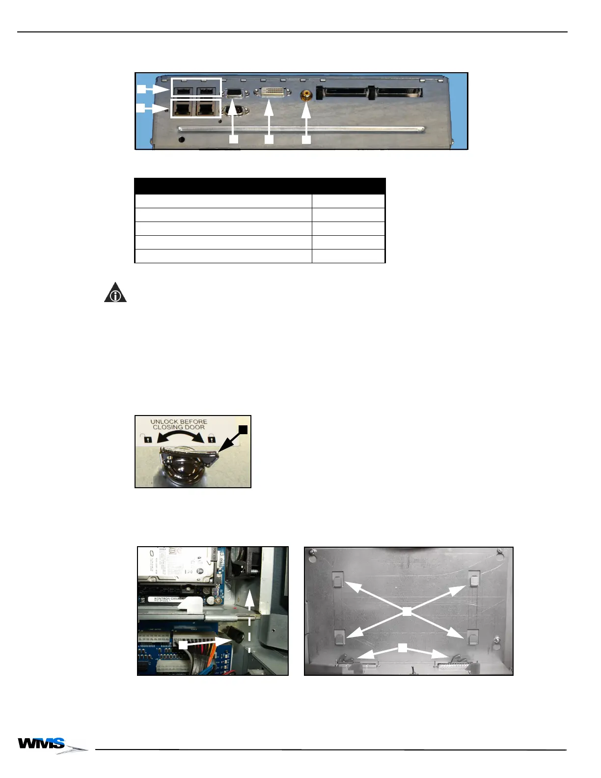
3 Disconnect the DVI Cable, Figure 2-4 (D), as defined in Table 2-1.
Figure 2-4 Connections to CPU-NXT2 (top) and CPU-NXT3 (bottom).
4 If applicable, disconnect the VGA Cable, Figure 2-4 (C), as defined in Table 2-1.
NOTE: After the VGA Cable is disconnected from the Accessory/Top Box LCD, it is to remain in the
game.
5 Disconnect the SPDIF Cable, Figure 2-4 (E), as defined in Table 2-1.
6 Disconnect the USB Cable, Figure 2-4 (A), as defined in Table 2-1.
7 If applicable, disconnect the Ethernet Cable, Figure 2-4 (B), as defined in Table 2-1.
8 Turn the CPU Lock to the left and open or remove the CPU Enclosure Logic Door,
Figure 2-5 (A).
Figure 2-5 Turning CPU Lock to the left to unlock.
9 Pull down and slightly forward to disengage hook, then push up on the black mounting tab
located below the CPU Enclosure, Figure 2-6 (A), on the right-hand side, to disengage the
CPU Enclosure from the two blind mate connectors on the Bulkhead Board, Figure 2-6 (B).
Figure 2-6 CPU Enclosure removal from the game.
10 Lift the CPU Enclosure up and away from the four hooks, Figure 2-6 (C), that hold the CPU
Enclosure in place.
11 Remove the CPU Enclosure from the game.
Table 2-1 CPU Assembly Connections.
Connection Location
USB Ports (4) Figure 2-4 (A)
Ethernet Ports (2) (if applicable) Figure 2-4 (B)
VGA Video Ports Figure 2-4 (C)
DVI Video Port Figure 2-4 (D)
SPDIF Port Figure 2-4 (E)
 Loading...