2-18
Chapter 2: Installation and Setup
Aug 2012
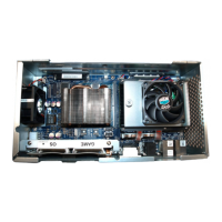
14 Route the DVI Cable through the cable clamp located along the back of the cabinet,
Figure 2-35 (A), and then through the cable access hole located on the bottom right,
Figure 2-35 (B).
Figure 2-35 Routing DVI Cable through cable clamps and down cable access hole (left) and cable access
hole close-up (right).
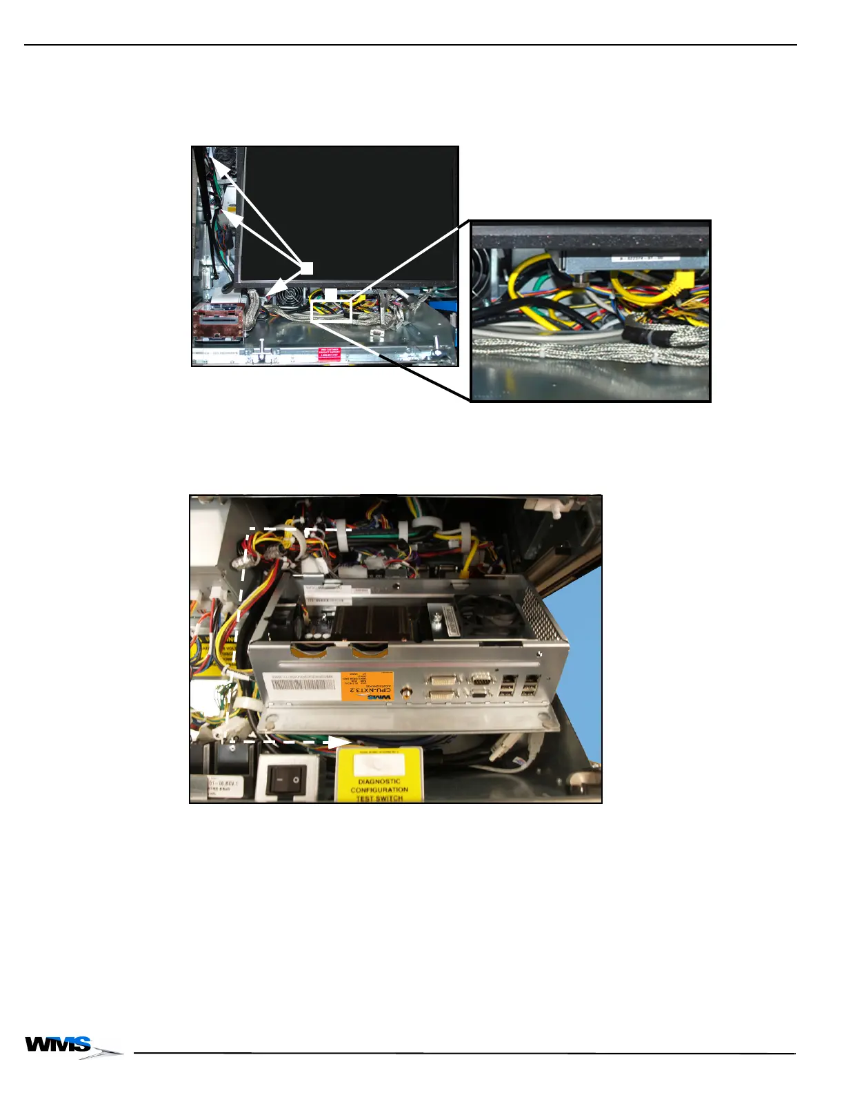
15 Continue routing the DVI Cable with the cable bundles, under the shelf and through the cable
clamps behind the right side of the Component Drawer keeping them as far away from the
main cable bundle as possible, Figure 2-36.
Figure 2-36 Connecting the Ethernet cables to CPU-NXT 3.2.
 Loading...