Manual 26166V1 MicroNet Simplex & MicroNet Plus
Woodward 18
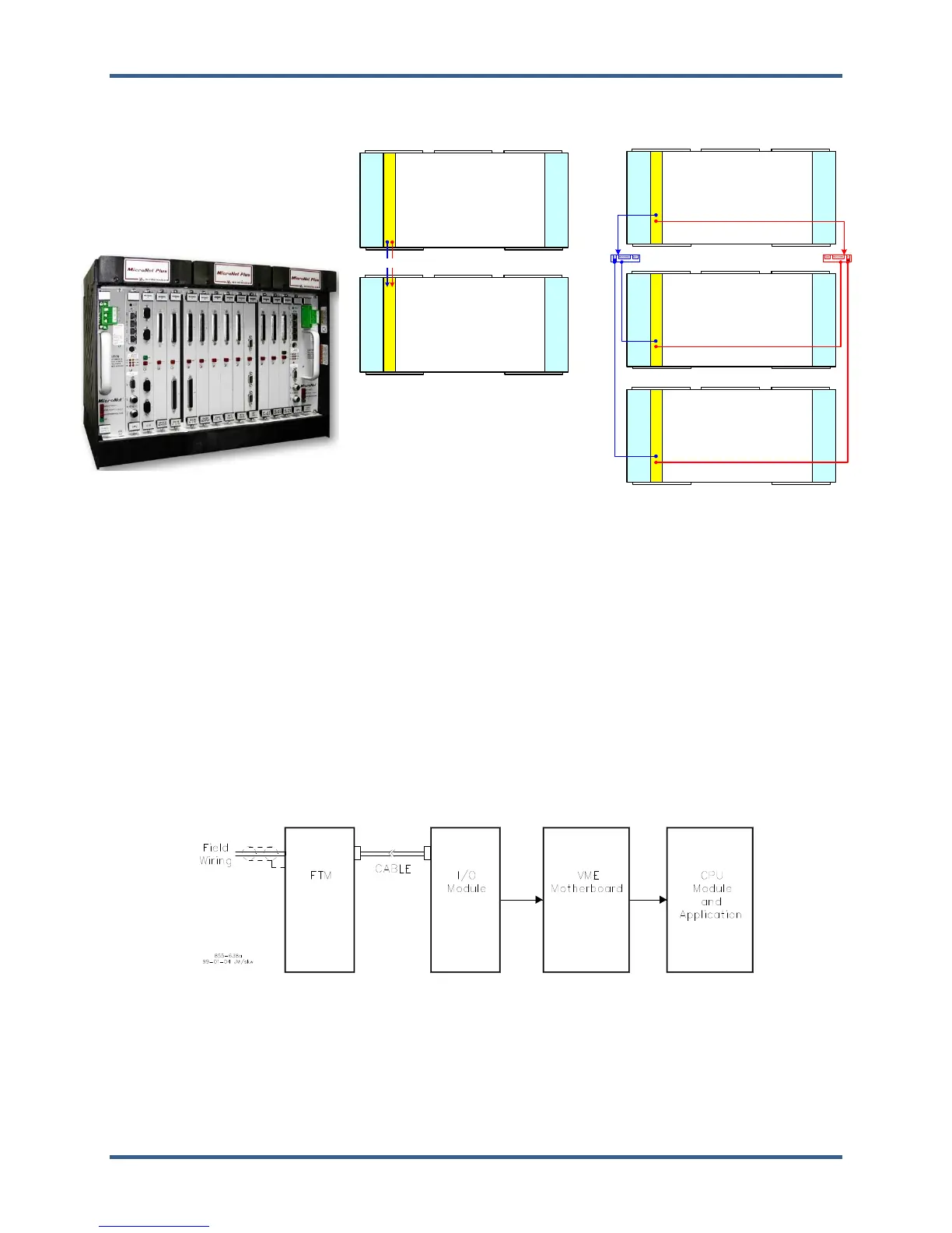
System Diagrams—MicroNet Plus Simplex
MicroNet Plus
MicroNet 14 or 8 VME Slot Chassis
Single CPU for simplex operation
Simplex or Redundant I/O modules
Simplex or Redundant Power
Redundant smart fans
MicroNet Plus - Simplex (2-rack)
FAN_2
FAN_1
FAN_3
FAN_4
FAN_6
CPU1
2-Slot
PS
PS1
2-Slot
PS
PS2
MicroNet Plus
- Main CPU rack
- Single CPU_5200
FAN_2FAN_1
FAN_3
FAN_4
FAN_6
RTN
A1
2-Slot
PS
PS1
2-Slot
PS
PS2
MicroNet Plus
- Expansion rack
- Single Remote RTN
RTN-1 and 2
FAN_2
FAN_1
FAN_3
FAN_4
FAN_6
RTN
A1
2-Slot
PS
PS1
2-Slot
PS
PS2
MicroNet Plus
- Expansion rack
- Single Remote RTN
FAN_2
FAN_1
FAN_3
FAN_4
FAN_6
CPU1
2-Slot
PS
PS1
2-Slot
PS
PS2
MicroNet Plus
- Main CPU rack
- Single CPU_5200
FAN_2
FAN_1
FAN_3
FAN_4
FAN_6
RTN
A1
2-Slot
PS
PS1
2-Slot
PS
PS2
MicroNet Plus
- Expansion rack
- Single Remote RTN
RTN1
SW
MicroNet Plus - Simplex (3-rack)
RTN2
SW
Figure 2-6. MicroNet Plus Simplex System Diagrams
2.3.1—Redundant Power Supplies
Two load sharing power supplies provide redundant power to the motherboard, CPU and I/O modules. The
MicroNet Plus power supplies are 2-slot wide each and are located at each end of the chassis in the
designated PS1 and PS2 slots.
2.3.2—Single CPU Options
The MicroNet Plus control system may be used in simplex mode with a single CPU module that must be
located in slot A1 of the main chassis. No other options are available.
2.3.3—Simplex Inputs and Outputs
Each I/O module has connectors on the faceplate. For analog and discrete I/O, cables connect the module
to a Field Terminal Module (FTM). The FTM is used to connect to the field wiring. For communication
modules, FTMs are not used. Cables are connected directly to the faceplate of the communications module.
The following diagram shows the flow of analog and discrete inputs from the field to the application.
Figure 2-7. Input Flow