Manual 26166V1 MicroNet Simplex & MicroNet Plus
Woodward 119
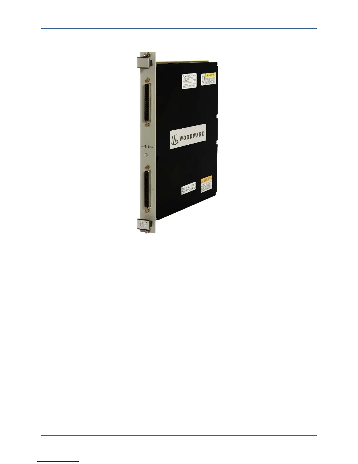
Figure 9-10. Speed/Analog IO Combo Smart-Plus Module
9.29.3—Installation
The modules slide into card guides in the control's chassis and plug into the motherboard. The modules
are held in place by two screws, one at the top and one at the bottom of the front panel. Also at the top
and bottom of the module are two handles which, when toggled (pushed outward), move the modules out
just far enough for the boards to disengage the motherboard connectors.
In a simplex system, each Speed/Analog IO Combo Smart-Plus Module is connected through one Low
Density Analog Cable to one Analog Input FTM and one High Density Analog Cable to one 24/8 Analog
FTM.
All of the I/O are accessible on the FTM and the channels are labeled to correspond to their software
locations (e.g., analog input 1 on the FTM will be analog input 1 in the application software). See Figure
9-73 for an example.