Manual 26166V1 MicroNet Simplex & MicroNet Plus
Woodward 89
Discrete Inputs
Each MicroNet Discrete I/O Smart-Plus module accepts 48 contact inputs. The 48/24 Discrete FTM may
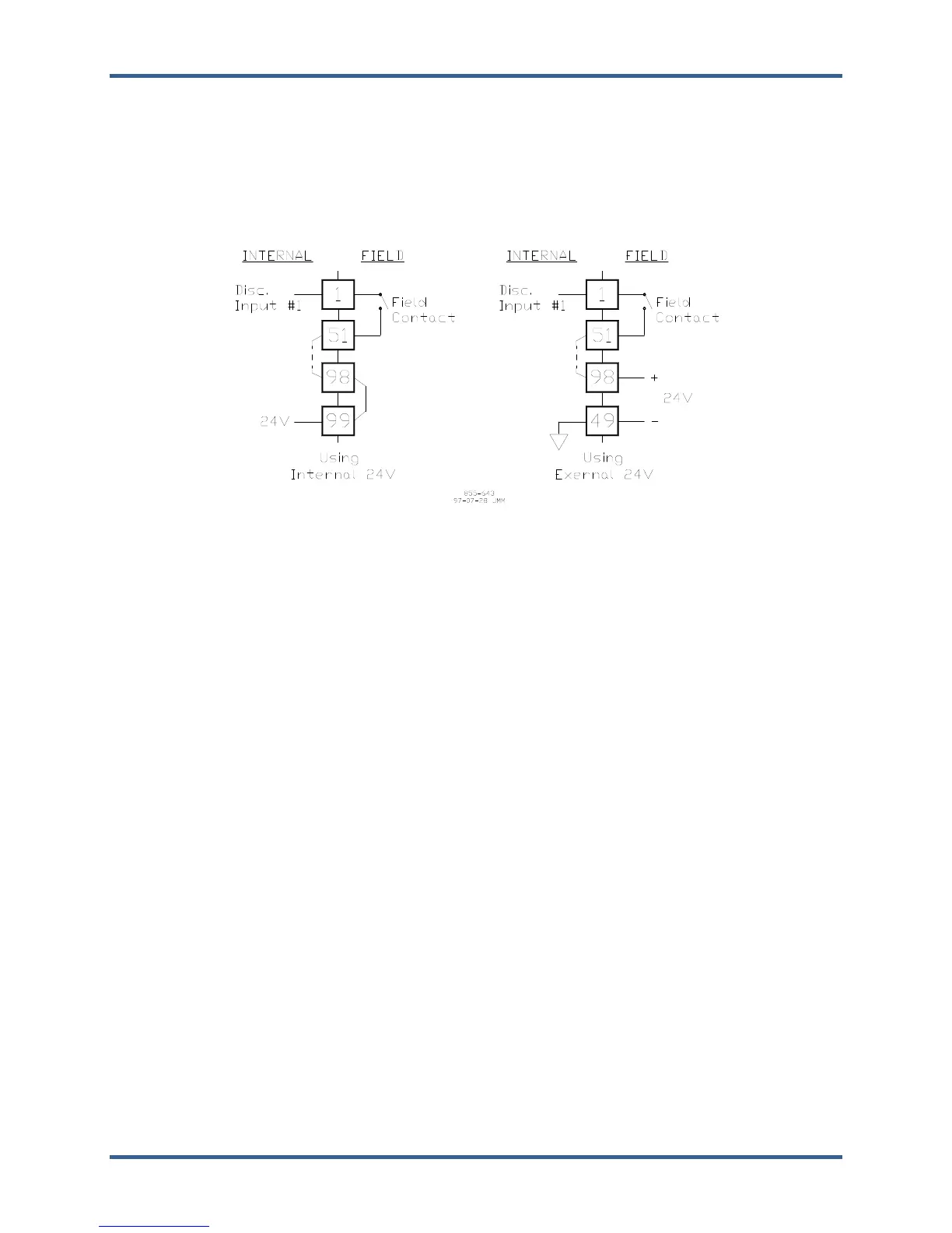
supply contact wetting voltage. Optionally, an external 18–32 Vdc power source. If the 24 Vdc internal
power source is used for contact wetting, a jumper is required between FTM terminals 98 and 99. If an
external power source is used for contact wetting, the external source common must be connected to the
FTM’s discrete input common, terminal 49. The FTM provides a common cage-clamp terminal connection
for customer field wiring. Figure 8-4 illustrates different discrete input wiring configurations based on the
input voltage.
Figure 8-4. Discrete Input Interface Wiring to a 24 Vdc 48/24 Discrete FTM
Configuration Notes:
Refer to Chapter 13 for Discrete Input wiring.
Each MicroNet Discrete I/O Smart-Plus module can only accept one input voltage range, 24 Vdc
(LVD and UL).
All contact inputs accept dry contacts.
24 Vdc FTM only—If the internal 24 Vdc is used, a jumper must be added to tie the internal 24 Vdc
to the bussed power terminal blocks (see Figure
8-4).
24 Vdc FTM only—If an external 24 Vdc is used, the common for the external 24 Vdc must be tied to
the discrete input common (see Figure 8-4). Power for contacts must be supplied by the control’s
power supplies, or the external power supply outputs must be rated to Class II at 30 Vdc or less and
outputs must be fused with appropriately sized fuses (a maximum current rating of 100 V, where V
is the supply’s rated voltage or 5 A, whichever is less).
Discrete Outputs
For the 48/24 Discrete Combo FTM configuration, there are three types of relay output boxes that can be
used. These consist of the 16Ch Relay (Phoenix) Module, 16Ch Relay Module, and the 32Ch Relay
Module (see Chapter 13 for a description of the available modules). The relay modules connect to the
48/24 Discrete FTM through individual cables and provide a common cage-clamp terminal connection for
customer field wiring. The discrete outputs on the 48/24 Discrete I/O module are non-isolated; the
isolation takes place in the relay boxes.
Discrete outputs 9, 10, 11, 12, 21, 22, 23, and 24, drive two relays per output (see Table 8-1). Internal
wiring on the 48/24 Discrete I/O FTM provides this dual relay functionality. The application software may
use these relays for outputs where extra relay contacts are needed, such as alarm or shutdown outputs.