Manual 26166V1 MicroNet Simplex & MicroNet Plus
Woodward 81
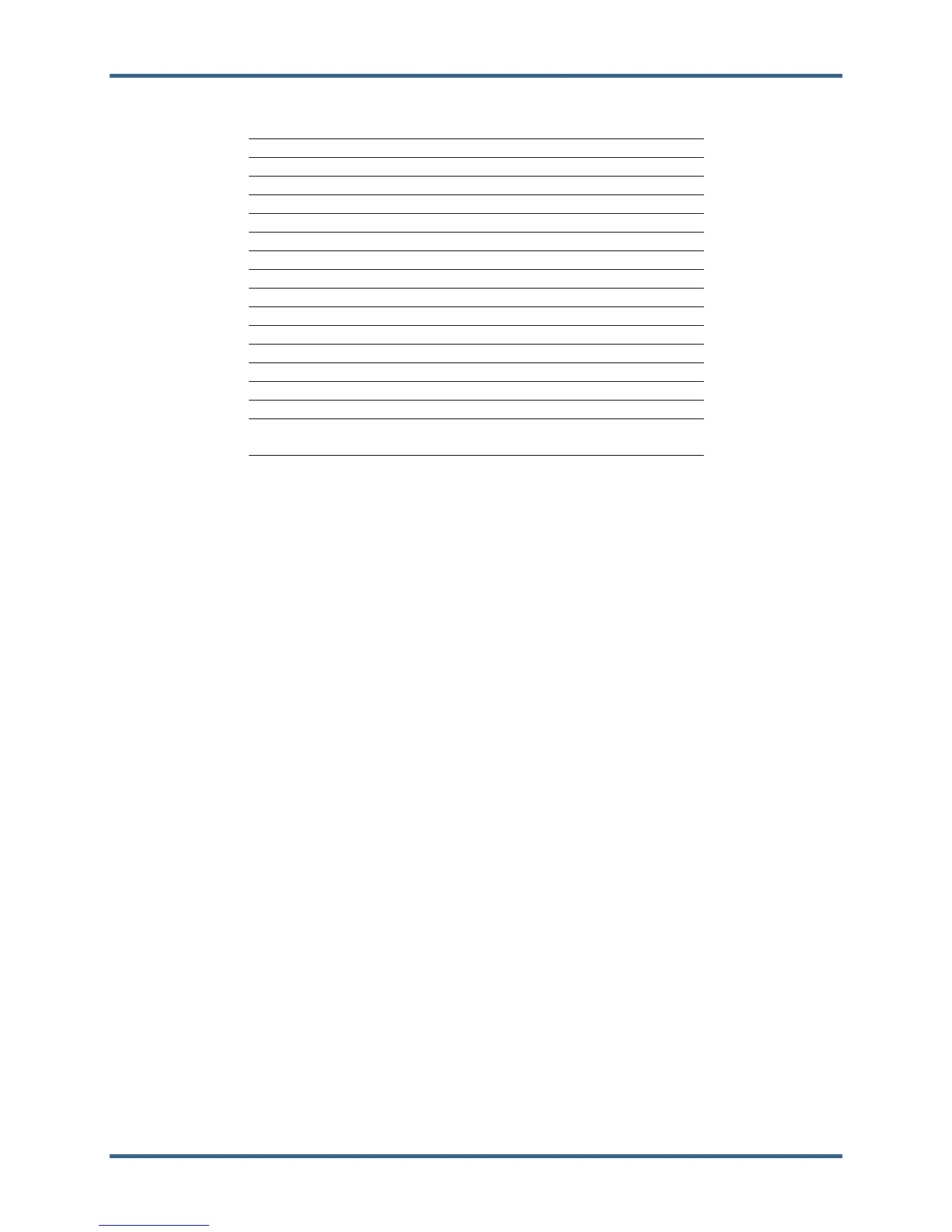
Table 7-3. RTN Fault LED Flash Codes
Failure Flash Code
RAM Test Failure 1, 4
Real Time Clock Test Failure 2, 2
Floating Point Unit Test Failure 2, 3
Flash Test Failure 2, 4
HD1 Flash Test Failure 2, 5
I2C Bus Test Failure 2, 6
Module Installed in wrong slot 2, 7
Main Chassis CPU switch must be set to 0 3,5
Remote RTN Rate Group 5 Slip 3, 7
Remote RTN Rate Group 10 Slip 3, 8
Remote RTN Rate Group 20 Slip 3, 9
Remote RTN Rate Group 40 Slip 3, 10
Remote RTN Rate Group 80 Slip 3, 11
Remote RTN Rate Group 160 Slip 3, 12
Remote RTN Chassis Switch Invalid 4, 5
Backup Remote RTN Chassis Switch different
from Primary Remote RTN
4, 6
This module does not support the CAN port(s) 4, 7
7.2—Simplex Main Transceiver (XCVR) Module
Module Obsolete. See Volume 3, Section 3 for information.
7.3—Simplex Remote Transceiver (XCVR) Module
Module Obsolete. See Volume 3, Section 3 for information.
7.4—Simplex Transceiver Accessories
Module Obsolete. See Volume 3, Section 3 for information.
7.5—Ethernet Module
Module Obsolete. See Volume 3, Section 3 for information.
7.6—SIO Module
7.6.1—Module Description
The SIO (Serial In/Out) Module interfaces four serial communication ports to the VME bus.
Figure 7-19 is a block diagram of the SIO module. The module manages four serial ports. Port a (J1) and
port B (J2) are RS-232 ports. Port C (J3) and Port D (J4) are for RS-232, RS-422, or RS-485
communication protocols. Ports C and D must be at the same baud rate when using 38.4 kBd or 57.6
kBd.
The processor on this module is a 68030. It controls the transfer of data between the ports and the VME
bus.
This module can have as much as 4 KB of Dual-Port RAM and 64 KB of PROM. The local memory
supports the 68030 processor on this module.
The SIO module has one LED (FAULT) and no switches.