Manual 26166V1 MicroNet Simplex & MicroNet Plus
Woodward 123
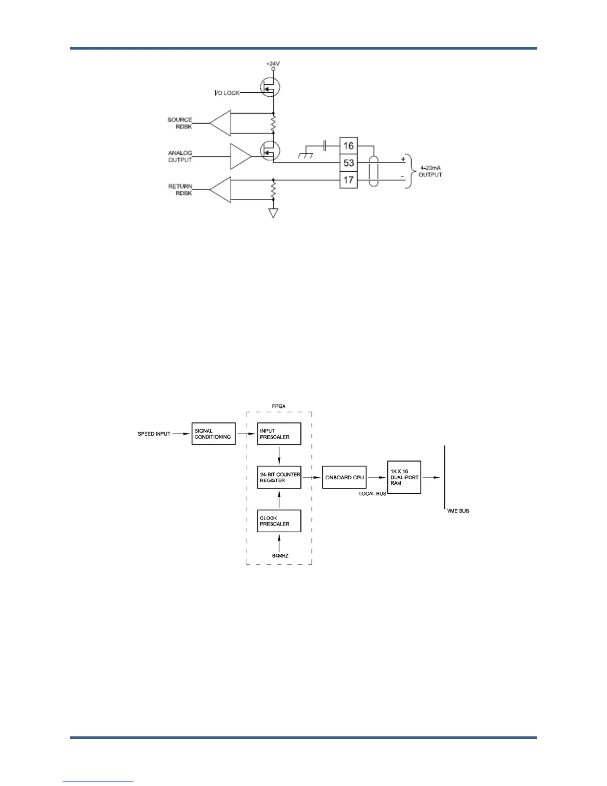
Figure 9-14. Analog Output Wiring for a 24/8 Analog FTM
9.29.5—Troubleshooting
Speed ranges are selected from the GAP and the signal is pre-scaled accordingly. The pre-scaled signal
then goes to a counter where the period of the signal is measured. The Digital Signal Processor samples
the counter's values every 100 microseconds and performs a divide to generate a digital speed signal.
Every 100 microseconds a digital-filter algorithm is executed to average the speed values in order to
improve speed-sensor resolution at input frequencies greater than 200 Hz. This digital filter also provides
a derivative output.
Once every rate time (5-200 ms typically), the latest speed and derivative information is moved to the
Dual-Port RAM for access by the CPU module.
Figure 9-15. Digital Speed Sensor Module Block Diagram
During initialization, which occurs after every reset, the CPU turns the FAULT LEDs on. The CPU then
tests each I/O module using diagnostic routines built into software. If the diagnostic test is not passed, the
LED remains on. If the test and initialization are successful, the LED goes off and green RUN LED is
turned on.