January 2016
4-3
WorkCentre WorkCentre 4150/4250/4260WorkCentre 4150/4250/42604150/
REP 1.1
Repairs and Adjustments
REP 1.1 Power Supply Unit 1 and HVPS (4150)
Parts List on PL 1.10
Removal
NOTE: This procedure should only be performed on the 4150. For the 4250/4260 procedure,
refer to the table of contents.
WARNING
Switch off the electricity to the machine. Disconnect the power cord from the customer
supply while performing tasks that do not need electricity. Electricity can cause death or
injury. Moving parts can cause injury.
WARNING
Take care during this procedure. Sharp edges may be present that can cause injury.
CAUTION
Before performing this procedure, refer to General Disassembly Precautions, GP 10.
1. Power off the machine. Disconnect the power cord.
2. Remove the exit tray assembly, PL 28.10 Item 1 or the finisher, REP 12.1.
3. Remove the paper exit cover, PL 28.10 Item 4.
4. Disconnect the following connectors from power supply unit 1 and the HVPS:
• CN1
•CON01
•CON1
•CON2
•CON71
•CON51
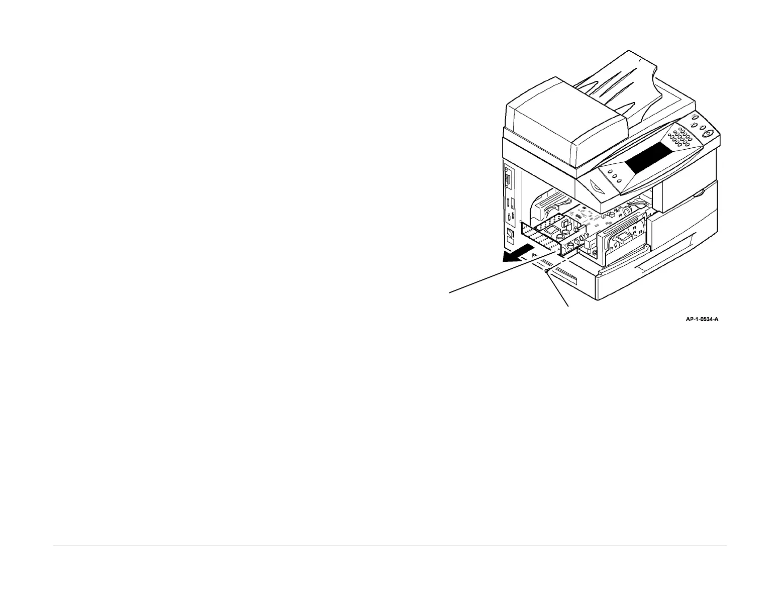
5. Remove power supply unit 1 and HVPS assembly, Figure 1.
Figure 1 Assembly removal
6. Remove power supply unit 1 from the support cage, PL 1.10 Item 9.
7. Remove HVPS from the support cage, PL 1.10 Item 9.
Replacement
CAUTION
Make sure that the AC connections are correct. The power input harness from the on/off switch
has a red male connector. This connects into the blue female connector (CON01) on power
supply 1. The power input harness from power supply unit 2 has a white male connector. This
connects into the white female connector (CON51) on power supply unit 1.
Replacement is the reverse of the removal procedure.
2
Remove power supply unit
1 and HVPS assembly.
1
Remove 1 screw.

 Loading...


