3-26
ENG
HANDLE AND WHEELS (FOR EF7200DE CAN)
6
2
3
4
5
1
4
7
a
1
1
2
3
2
1
2
3
2
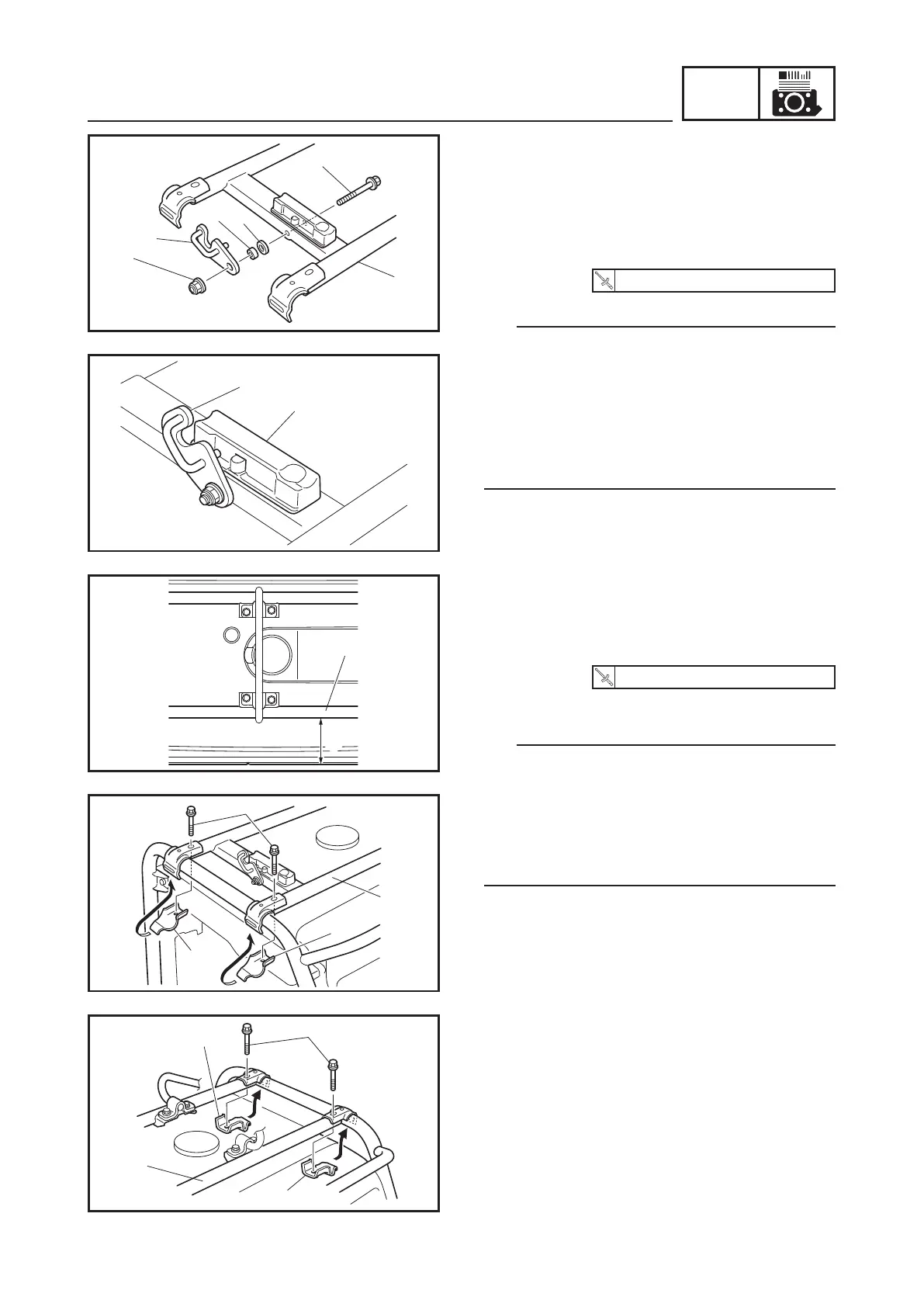
3. Install:
9 Lock lever bolt 1
9 Washer 2
9 Collar 3
9 Lock lever 4
9 Lock lever nut 5
16 Nm (1.6 m · kgf, 12 ft · lbf)
TIP
9 Insert the lock lever bolt 1 into the carrier
frame 6, and then put the washer 2, collar
3, and lock lever 4 in this order, and tight-
en the lock lever nut 5.
9 Make sure that the collar 3 is placed into
the washer 2.
9 Lock lever pin should be above stopper 7.
4. Install:
9 Carrier frame 1
9 Plate 2
9 Plate bolts 3
16 Nm (1.6 m · kgf, 12 ft · lbf)
a 10 cm (3.94 in)
TIP
9 Place the carrier frame 1 10 cm (3.94 in)
from the end of generator body.
9 Place the carrier frame 1 assembled to this
point on the generator body, and then fas-
ten the plate 2 to the carrier frame 1 with
the plate bolts 3.


 To Next Page