CABLE ROUTING
SPEC 0*
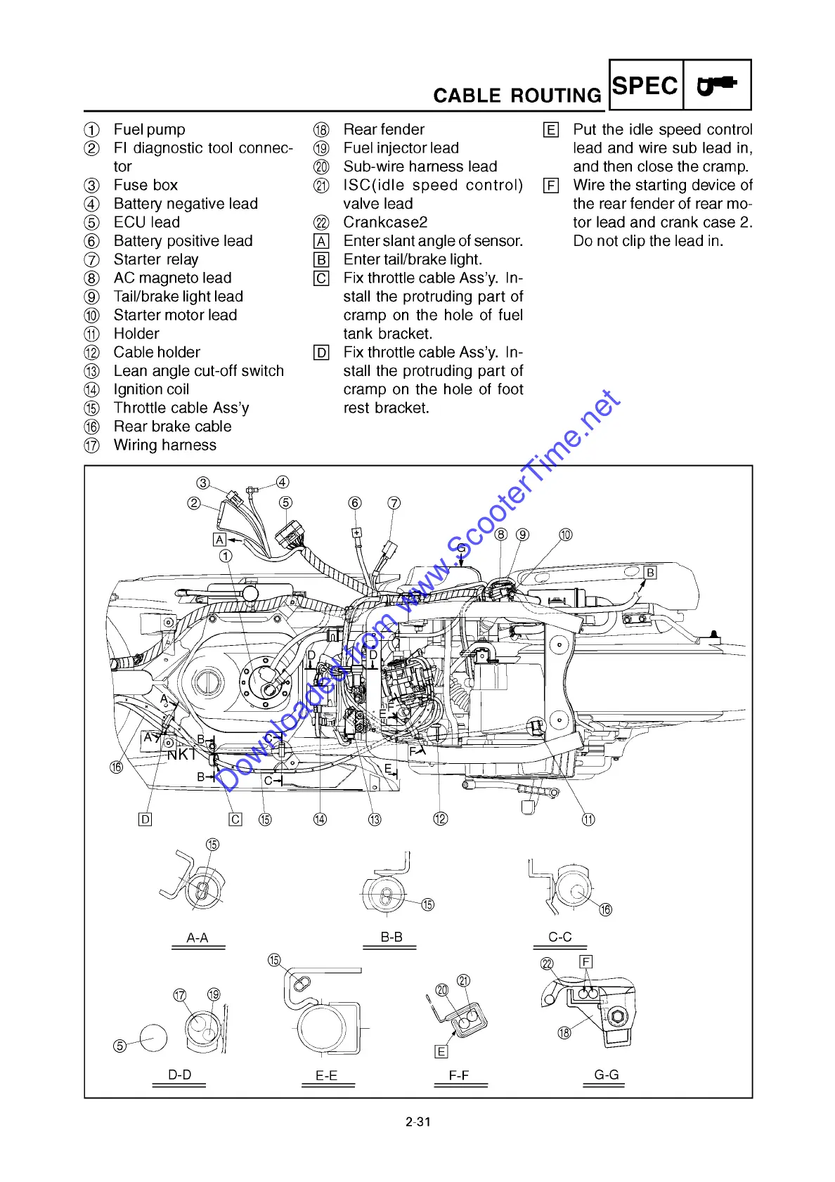
1 Fuel pump i Rear fender E Put the idle speed control
2 FI diagnostic tool connec- o Fuel injector lead lead and wire sub lead in,
tor p Sub-wire harness lead and then close the cramp.
3 Fuse box a ISC(idle speed control) F Wire the starting device of
4 Battery negative lead valve lead the rear fender of rear mo-
5 ECU lead s Crankcase2 tor lead and crank case 2.
6 Battery positive lead A Enter slant angle of sensor. Do not clip the lead in.
7 Starter relay B Enter tail/brake light.
8 AC magneto lead C Fix throttle cable Ass’y. In-
9 Tail/brake light lead stall the protruding part of
0 Starter motor lead cramp on the hole of fuel
q Holder tank bracket.
w Cable holder D Fix throttle cable Ass’y. In-
e Lean angle cut-off switch stall the protruding part of
r Ignition coil cramp on the hole of foot
t Throttle cable Ass’y rest bracket.
y Rear brake cable
u Wiring harness
dx
©-
©
D
C ©
®
© © ©
©
A-A
B-B
y
C-C
t
u
o
5
s
F
p
a
E
D-D
E-E F-F
G-G
2-31
Downloaded from www.ScooterTime.net
 Loading...